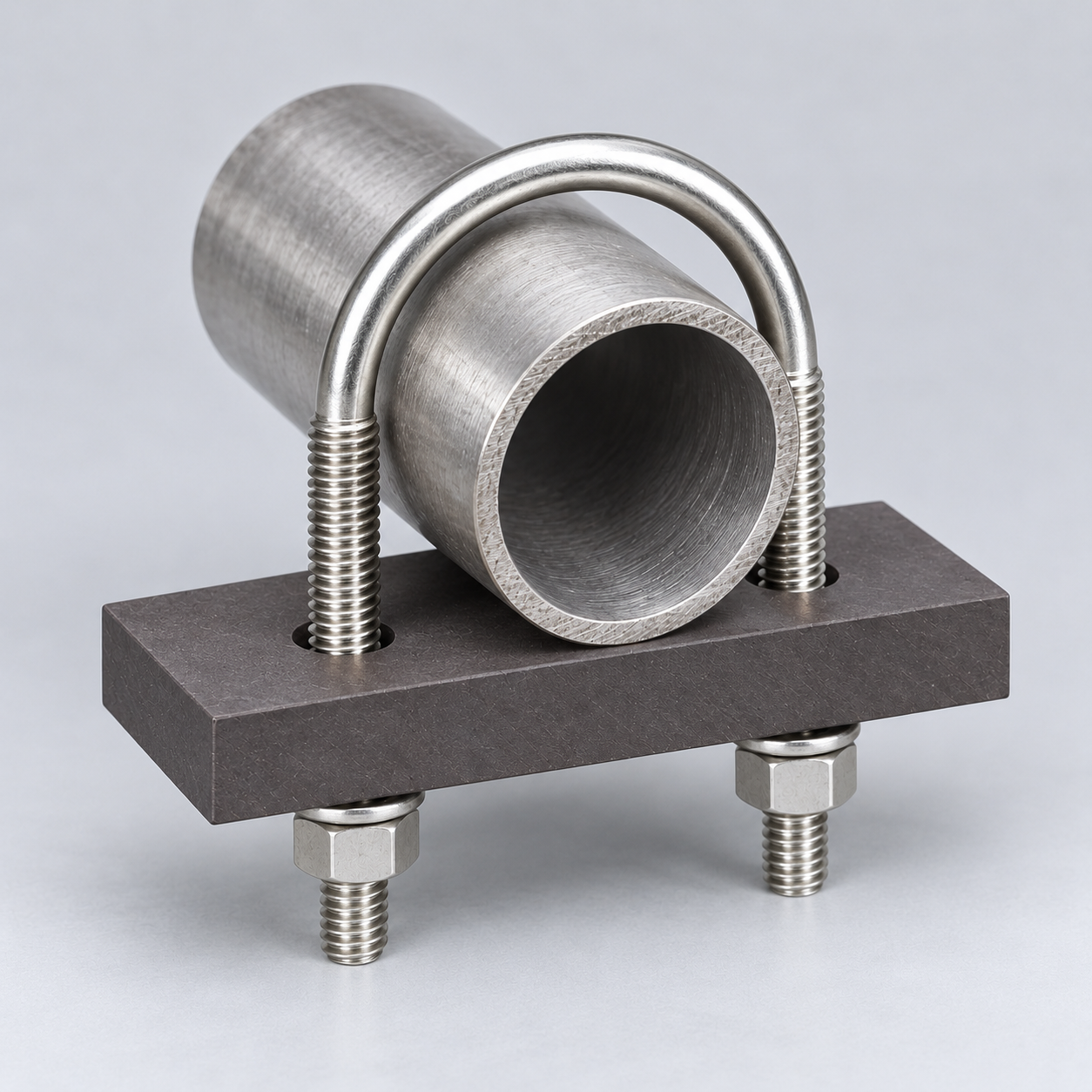
A U-bolt pipe support with graphite slide pad is a low-profile assembly that places a project-specified graphite bearing element between the pipe and support steel while a round U-bolt controls lift and lateral movement. YOUNGLEE supplies the U-bolt, drilled flat pad, nuts and washers as a drawing-defined set for hot process piping, heater areas, utility lines and other locations where a polymer contact element may not be appropriate. The graphite grade, atmosphere, contact pressure, movement, pipe temperature and heat path must be reviewed together: “graphite” alone does not establish a temperature rating, friction value or allowable load. Dimensions, materials, clearances and attachment details can be customized to the approved installation drawing.
Image note: the featured image is a transformed representative catalog visual based on a YOUNGLEE-owned photograph of a U-bolt and dark drilled pad. It illustrates the general pipe-on-pad arrangement; it does not verify a graphite grade, dimension, load, friction coefficient, temperature limit, test, certification, stock item or previous project.
U-Bolt and Graphite Pad Assembly at a Glance
| Selection Item | Typical YOUNGLEE Supply Basis | Information for Buyer Confirmation |
|---|---|---|
| Product type | Round U-bolt, flat drilled graphite pad, nuts and washers supplied as a coordinated pipe-support set | Approved drawing, quantity, pipe orientation and support-steel interface |
| Primary function | Pipe bearing surface plus lateral and uplift control; axial sliding may be permitted where designed | Support, guide, hold-down or grip duty; permitted movement and load directions |
| Pipe basis | Actual bare pipe OD or finished insulated OD, not NPS/DN alone | NPS/DN, actual OD, wall/schedule, pipe material and operating movement |
| U-bolt options | Carbon steel, alloy steel, 304/304L or 316/316L stainless steel; finish selected separately | Material specification, grade, heat treatment, coating, traceability and test documents |
| Pad options | Machined graphite or carbon-graphite grade selected for the stated bearing and environment | Grade/TDS, density, compressive data, oxidation resistance, electrical behavior and acceptance criteria |
| Geometry | Custom rod diameter, thread, inside width, leg length, thread length, bend radius, pad length/width/thickness and hole spacing | Dimensioned drawing, tolerances, installation access and support-member thickness |
| Service review | Project-specific because pad performance depends on grade, contact pressure, counterface, movement, temperature and atmosphere | Normal/upset temperature, atmosphere, vertical reaction, side load, uplift, travel, cycles and maintenance plan |
| Inspection | Dimensional, visual and material-document checks; additional inspection where specified | ITP, certificates, sampling, coating inspection, marking and packing requirements |
Customization Note: The configurations and technical items above are for selection and quotation reference. Actual dimensions vary with the applicable drawing or standard, actual pipe outside diameter, grip or non-grip function, pad thickness, support steel, installation arrangement, temperature and project loads. YOUNGLEE can manufacture U-bolts and graphite-pad assemblies to customer drawings, specifications, samples or confirmed installation conditions. Buyers may specify U-bolt material, rod diameter, thread, inside width, leg length, thread length, bend radius, finish, graphite grade, pad dimensions, hole spacing and inspection requirements subject to technical review.
What Engineering Problem Does the Graphite Pad Address?
The pad separates the pipe from the structural bearing surface and can provide a replaceable contact element in a compact U-bolt support. In a guide arrangement, the pipe bears vertically on the pad while controlled clearance between the pipe and U-bolt allows axial movement. The U-bolt then limits lateral displacement and uplift rather than being tightened to generate an unspecified clamping force.
Industry pipe-support catalogs also use graphite as an optional slide-plate material in U-bolt cradle assemblies. That establishes a recognizable procurement configuration, but it does not make one supplier’s dimensions, bonding method, friction value or load table universal. YOUNGLEE therefore treats the pad geometry and its retention method as drawing-defined items.
The complete load path must be checked
The vertical reaction travels from the pipe wall into the graphite contact area, through the pad and into the supporting steel. Lateral or uplift forces may then engage the U-bolt, nuts, washers, pad holes and supporting member. A strong U-bolt does not correct an undersized pad, excessive edge pressure, inadequate support steel, poor hole clearance or a brittle pad detail. Pipe local stress, pad bearing pressure, pad bending, hole-edge distance, fastener stress and the support member all require coordinated review.
Why Graphite Grade and Atmosphere Matter
Graphite is a material family, not a single specification. Commercial grades can differ in apparent density, porosity, particle size, impregnation, compressive strength, thermal conductivity and oxidation resistance. Published graphite-manufacturer data also shows that oxidation behavior depends on temperature, impurities, density, exposed surface area and atmosphere. A temperature quoted for one purified or oxidation-inhibited grade must not be transferred to an unidentified pad.
For this reason, the quotation should identify the proposed graphite or carbon-graphite grade and attach its technical data sheet. The review should use the pad’s actual contact temperature, not only the pipe fluid temperature. Insulation, heat shields, conduction through the U-bolt, ventilation, start-up transients and outdoor air exposure can materially change the pad condition.
Graphite is not an electrical isolation material by default
Graphite is electrically conductive. If the design objective is galvanic isolation or electrical separation, a graphite pad should not be assumed to perform the same job as an insulating phenolic or thermoplastic support. The buyer should state whether electrical continuity, bonding or isolation is required and select the complete interface accordingly.
Graphite, PTFE and Phenolic Contact Elements Compared
| Contact Element | Typical Selection Direction | Important Limitation | Information for Buyer Confirmation |
|---|---|---|---|
| Graphite or carbon-graphite pad | Considered where a project needs a dry contact or sliding element and the specified grade suits the temperature and atmosphere | Grade-dependent oxidation, strength and wear; electrically conductive; brittle edge and hole details need review | Grade/TDS, atmosphere, contact temperature, pressure, travel, counterface and retention |
| PTFE-based slide material | Often selected for low-friction sliding within a verified temperature and pressure range | Creep, edge loading, adhesive limits and temperature depend on formulation and backing | Compound, mating plate, pressure, speed/travel, temperature and attachment |
| Phenolic-laminate or engineered polymer bar | Often used for load spreading, corrosion control or electrical separation where the grade is suitable | Temperature, moisture behavior, strength and electrical properties vary by grade and reinforcement | Laminate/polymer grade, profile, bearing area, insulation requirement and environment |
| Direct steel-on-steel contact | Simple bare-pipe support where friction, wear and corrosion risk are acceptable | Can concentrate load and create coating damage, fretting or crevice-corrosion concerns | Pipe/support materials, coating, movement, wear allowance and inspection access |
Customization Note: This comparison is a selection aid, not a universal ranking. Final material, dimensions and attachment depend on the actual pipe OD, load, movement, counterface, environment, temperature and project specification. YOUNGLEE can manufacture the U-bolt and pad arrangement to an approved drawing after the buyer confirms these conditions.
Grip, Hold-Down and Non-Grip Guide Options
A graphite pad does not decide the U-bolt function. That function comes from the installed clearances, nut positions and load cases:
- Non-grip guide: controlled side and top clearance permits axial thermal movement while limiting lateral travel and uplift.
- Hold-down: the U-bolt resists a specified uplift case without applying a continuous crushing force to the pipe.
- Grip or restraint: the assembly is intentionally tightened to develop contact. This option needs a defined installation procedure and checks for pipe-wall stress, pad response and relaxation.
“Snug tight” is not a universal torque. Lubrication, thread finish, nut grade, coating and prevailing friction can change the relationship between torque and bolt tension. Where pretension matters, the project engineer should provide an approved tightening method and acceptance criterion.
Dimensions Required for a Buildable Drawing
| Dimension or Input | Why It Matters | Information for Buyer Confirmation |
|---|---|---|
| Actual pipe OD | Controls U-bolt inside width, bend geometry and functional clearance | Cold and operating OD; do not provide NPS/DN alone |
| Rod diameter and thread | Affects holes, nuts, bendability, available section and installation access | Metric or inch series, pitch, thread class and required engagement |
| Inside width and bend radius | Establishes pipe fit and spacing between legs | Finished dimension after coating and tolerance |
| Leg and thread length | Must accommodate pad/support thickness, washers, nuts and adjustment | Datum, tangent length, threaded length and projection after assembly |
| Pad length, width and thickness | Controls contact area, stability and edge distance around holes | Machined size, flatness, surface finish and tolerances |
| Hole diameter and spacing | Controls fit around the legs and remaining graphite ligament | Hole tolerance, chamfer/radius and crack-rejection criteria |
| Movement and loads | Determine guide clearance, contact pressure and required support checks | Vertical, lateral, uplift and occasional loads; axial travel and cycles |
Customization Note: The listed dimensions are quotation inputs, not a fixed product series. Actual values vary with pipe OD, U-bolt function, graphite pad thickness, support steel, loads, thermal travel and installation arrangement. YOUNGLEE can manufacture to customer drawings, specifications, samples or confirmed conditions. If dimensions are supplied in inches, YOUNGLEE retains every decimal place provided and converts to millimetres by multiplying the original inch value by exactly 25.4, without rounding the inch input first.
Material and Standard Boundaries
The order should name what each standard governs. ISO 898-1 addresses specified mechanical properties of carbon- and alloy-steel bolts, screws and studs at its stated ambient test range; it does not by itself establish corrosion resistance, fatigue performance or high-temperature capacity. ISO 3506-1 addresses corrosion-resistant stainless-steel fasteners and likewise requires additional review outside its stated temperature basis. ASTM A193/A193M may be specified for certain alloy- or stainless-steel bolting in high-temperature, high-pressure or special-purpose service, but selecting an A193 grade does not rate the graphite pad or the complete support.
The U-bolt material, nuts, washers, graphite pad and support steel must therefore be identified separately. Coating a carbon-steel U-bolt may improve corrosion protection, but coating thickness and thread allowance must be considered. Stainless steel can reduce some corrosion risks, yet chloride exposure, crevices, temperature and dissimilar-metal contact still require project review.
Manufacturing and Inspection Considerations
Useful production controls include verifying bar and pad material documents, forming to the approved bend radius, checking leg parallelism and inside width, confirming thread fit before and after finishing, and inspecting pad dimensions, flatness, hole position and visible edge damage. Graphite machining should avoid sharp, unsupported details where the drawing permits a radius or chamfer. Packaging should prevent metal legs from impacting the pad during transport.
For critical service, the inspection plan may add dimensional reports, positive material identification for metallic parts, coating-thickness checks, thread gauges, graphite grade certificates and an assembly-fit check. These checks confirm conformity to the purchase specification; they do not create a load rating unless the design and test basis are also defined.
Related U-Bolt Support Configurations
Where the pipe needs elevation, a defined shoe load path or a separate lower slide interface, review the U-bolt pipe shoe for non-welded support. For a nonmetallic load-spreading bar selected mainly for insulation or corrosion control, compare the phenolic-laminate support-bar U-bolt assembly. When the fastener itself requires a high-temperature alloy grade, the ASTM A193 Grade B16 alloy-steel U-bolt explains the separate bolting-material decision.
Frequently Asked Questions
Can one maximum temperature be stated for the assembly?
No. The limit depends on the identified graphite grade, atmosphere, oxidation behavior, contact pressure, attachment method, pipe heat path, U-bolt material, nuts, coating and required service life. Submit the pad TDS and normal/upset temperatures for review.
Does the pipe slide on the graphite pad?
It can when the support is designed as a non-grip guide and the pad/counterface are approved for the movement. Travel direction, contact pressure, surface condition, friction basis and wear allowance must be specified.
Can graphite provide galvanic isolation?
Do not assume so. Graphite is conductive. If electrical or galvanic isolation is required, state that requirement and select a verified insulating system.
Is NPS or DN enough to size the U-bolt?
No. Quote the actual pipe OD. Also provide rod diameter, inside width, leg length, thread length, bend radius, pad thickness, guide clearance and tolerances.
Can YOUNGLEE supply a different pad profile?
Yes, flat, radiused or drawing-defined contact pieces can be reviewed. The final profile must suit the pipe contact area, graphite grade, machining limits, loads and retention method.
Request a Quotation
Send YOUNGLEE the pipe NPS/DN and actual OD, pipe material and wall, U-bolt rod diameter and thread, inside width, leg length, thread length, bend radius, metal grade and finish, graphite grade/TDS, pad dimensions, support-steel detail, guide or grip function, normal and occasional loads, axial travel, temperature, atmosphere, quantity, drawing, inspection requirements and packaging needs. YOUNGLEE will review the complete U-bolt and graphite-pad configuration for production to the approved drawing or applicable specification.