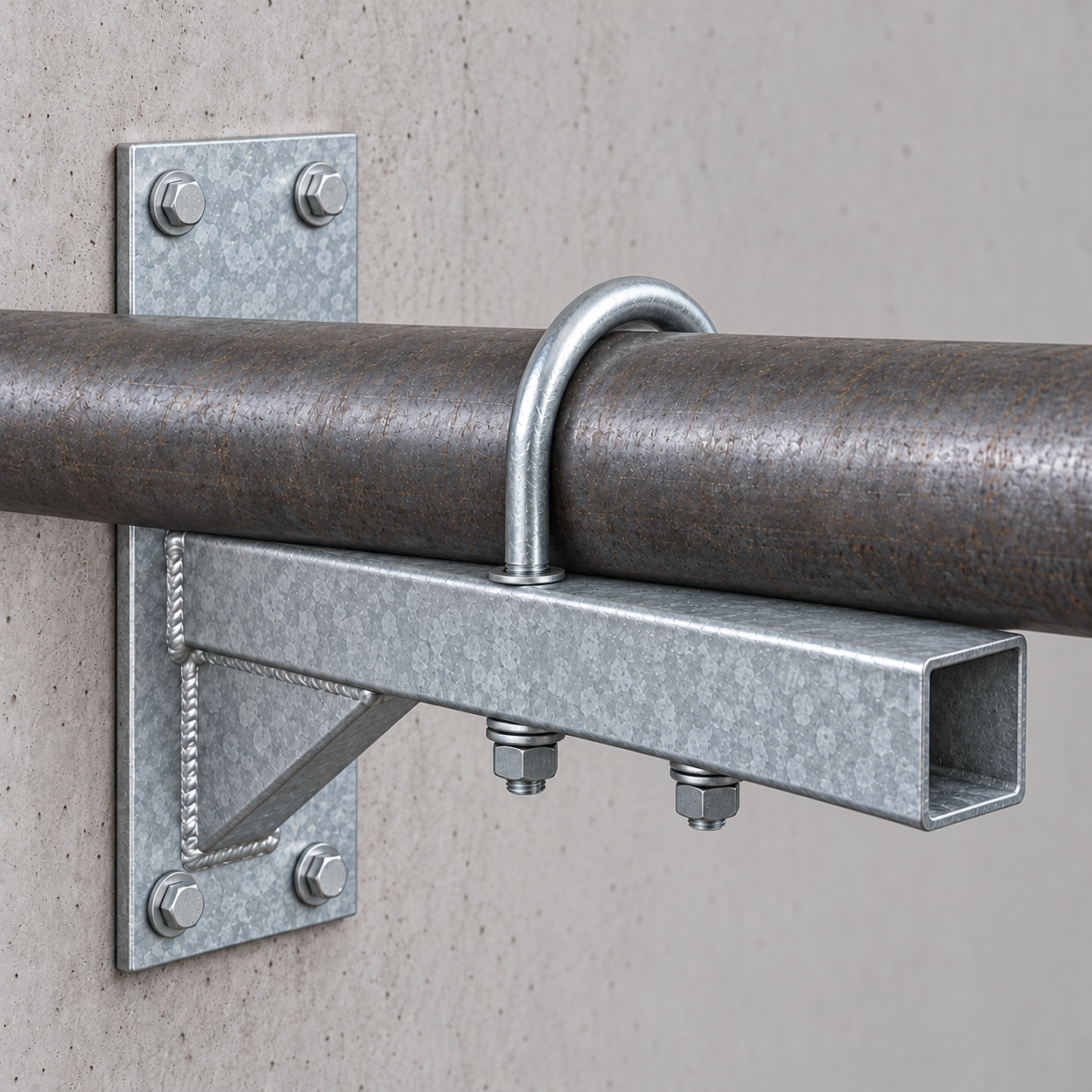
A wall-mounted U-bolt pipe support bracket combines a fabricated cantilever bracket with a round U-bolt to support and retain a horizontal pipe beside a wall or structural face. YOUNGLEE supplies the welded bracket, U-bolt, nuts, washers, optional pipe-contact plate, and project-defined finish as a drawing-controlled assembly. The bracket carries the vertical reaction back to the wall, while the U-bolt can be configured as a hold-down, guide, or grip restraint according to the approved piping-support design. Typical uses include process piping, utility services, water lines, equipment skids, plant rooms, and locations where floor space is limited. Arm length, pipe centerline offset, material, coating, U-bolt dimensions, anchor interface, and support behavior are customized after the buyer confirms loads, movement, pipe OD, wall construction, and installation conditions.
Image note: the featured image is a generated representative configuration showing a bare steel pipe retained on a galvanized, gusseted wall bracket by a round U-bolt. It illustrates the component arrangement only; it does not verify a project dimension, material grade, anchor design, load rating, coating thickness, test, certification, or previous supply.
Wall-Mounted U-Bolt Pipe Support Bracket at a Glance
| Selection item | Typical custom supply basis | Information for Buyer Confirmation |
|---|---|---|
| Product type | Welded cantilever wall bracket with one round U-bolt, nuts and washers; optional contact plate or saddle | Assembly drawing, quantity, pipe orientation and installation access |
| Primary function | Support the pipe from below and retain its position relative to the bracket | Vertical, lateral, axial, uplift, occasional and test-load cases |
| Support behavior | Grip, hold-down, guide or clearance arrangement, depending on U-bolt fit and tightening instructions | Required movement directions, clearances, restraint forces and installation torque policy |
| Pipe basis | Bare pipe OD or finished insulated OD; nominal size alone is not a complete fit dimension | Actual OD, NPS or DN, wall or schedule where relevant, insulation and tolerance |
| Bracket construction | Welded plate, angle, channel or rectangular-section arm with wall plate and gusset | Arm projection, pipe centerline offset, elevation, plate sizes, weld details and edge clearance |
| U-bolt geometry | Round bend or drawing-defined shape with two threaded legs | Rod diameter, inside width, inside height, leg length, thread length, thread form and bend radius |
| Materials | Carbon-steel bracket and U-bolt; stainless-steel or mixed-material options available after compatibility review | Separate material specifications for bracket, U-bolt, nuts, washers and anchors |
| Finish | Plain, painted, zinc-plated hardware, hot-dip-galvanized fabrication, stainless finish or project system | Coating standard, thickness, color, touch-up method and environment |
| Reference framework | ANSI/MSS SP-58 may govern the support system when adopted; material and coating standards apply only to their stated scope | Applicable edition, support detail, design basis, inspection and documentation |
| Customization | Manufacture to buyer drawing, support schedule, sample or confirmed installation data | Marking, packing, matching hardware and approval-document requirements |
Customization Note: The dimensions and technical values listed above are for selection and quotation reference. Actual dimensions vary with the applicable standard, actual pipe outside diameter, grip or non-grip design, insulation thickness, bracket projection, wall construction, installation arrangement, load, movement and project requirements. YOUNGLEE can manufacture wall-mounted U-bolt pipe support brackets according to customer drawings, specifications, samples or confirmed installation conditions. Buyers may specify bracket material and profile, plate thickness, gusset geometry, rod diameter, U-bolt inside width, leg length, thread length and form, contact plate, anchors, coating, lining and other requirements subject to technical review.
How Does the Wall Bracket Carry the Pipe Load?
The pipe bears on the top arm, a contact plate, or a formed saddle. That bearing reaction travels through the cantilever arm and gusset into the wall plate, then through the project-designed anchors or through-bolts into the supporting structure. The U-bolt is only one part of this load path. Tightening it does not compensate for an undersized arm, insufficient weld, weak wall substrate, poor anchor edge distance, or an unsuitable bearing surface.
The offset from the wall to the pipe centerline creates a bending moment in the arm and wall connection. Increasing the projection usually increases that moment even if pipe weight is unchanged. The designer must also consider contents, insulation, valves, hydrotest or other test condition, thermal displacement, occasional forces, vibration, uplift and maintenance loads. YOUNGLEE therefore treats the bracket geometry and attachment interface as drawing-controlled rather than assigning one universal capacity to every custom assembly.
What Does the U-Bolt Do in This Assembly?
The U-bolt passes around the pipe and through holes or docking features in the bracket arm. Nuts below the arm set the installed relationship between the pipe and support. Depending on the approved detail, the U-bolt may clamp the pipe, prevent uplift while leaving controlled clearance, or act as a lateral guide. These functions are not interchangeable.
Grip or fixed restraint
A grip arrangement develops contact around the pipe and may resist relative movement. Final tightening, pipe-wall sensitivity, coating damage, local pipe stress and restraint forces require engineering confirmation. A U-bolt should not be described as a fixed anchor unless the complete support, anchors and surrounding piping system are designed for the applicable reactions.
Hold-down or non-grip guide
A hold-down arrangement limits uplift while a guide arrangement controls lateral position and permits intended axial movement. Clearance can be established by inside dimensions, stop nuts, sleeves, spacers or an approved installation procedure. The drawing should define the permitted gap and whether nuts are locked against one another, against the support plate, or to a specified torque.
Critical Dimensions for Fit and Installation
| Dimension or condition | Why it matters | Information for Buyer Confirmation |
|---|---|---|
| Actual pipe OD | Controls U-bolt inside width, bend fit and bearing contact | OD plus NPS or DN; identify coating, ovality and tolerance |
| Finished insulated OD | Controls clearance when the U-bolt is outside insulation | Insulation type and thickness, jacket, shield or load-bearing insert |
| Wall-to-pipe centerline | Sets cantilever projection and connection moment | Required centerline offset and clearance from wall finishes or obstructions |
| Bracket arm section | Influences strength, stiffness, drilling, weld access and coating drainage | Plate, angle, channel or hollow section; thickness and orientation |
| Wall plate and holes | Transfer reactions to anchors or through-bolts | Plate dimensions, hole pattern, hole diameter, edge distance and back-plate requirement |
| Gusset geometry | Stiffens the arm-to-wall-plate junction | Number, thickness, length, weld size and interference limits |
| U-bolt rod and threads | Control fit, nut engagement, coating allowance and local contact | Rod diameter, bend radius, inside dimensions, legs, thread length and thread standard |
| Pipe contact interface | Affects pressure distribution, coating wear and sliding behavior | Bare arm, formed saddle, wear pad, liner, sleeve or isolation requirement |
Customization Note: These dimensional items are quotation and drawing-review inputs, not a universal size series. Final values depend on actual pipe outside diameter, insulation build-up, grip or guide function, load cases, wall condition, anchor arrangement, fabrication method and project specifications. YOUNGLEE can manufacture the bracket and U-bolt to a customer drawing or jointly confirmed installation envelope. Inch dimensions supplied by the buyer are retained at their stated precision and converted to millimetres by multiplying the original value by exactly 25.4, without rounding the inch input.
Material and Corrosion-Protection Options
| Option | Where it may be considered | Specification boundary | Information for Buyer Confirmation |
|---|---|---|---|
| Carbon-steel fabricated bracket | Indoor plant rooms, utilities and general industrial support frames | ASTM A36/A36M is one possible structural plate, bar or shape specification when selected; it does not rate the completed bracket | Exact material grade, product form, thickness, weld procedure and documentation |
| Carbon-steel U-bolt | General service with a compatible finish | Rod or fastener material must be specified separately from the bracket plate | Material standard and grade, thread class, heat treatment if any, nuts and washers |
| 304/304L stainless steel | Clean, wet or moderately corrosive service after environment review | Grade selection alone does not establish assembly load or prevent every corrosion mechanism | Grade, product specification, finish, fabrication, chloride exposure and traceability |
| 316/316L stainless steel | More demanding moisture or chloride conditions where the project specifies it | Still requires review for pitting, crevices, chemical exposure and dissimilar-metal contact | Grade, surface finish, passivation if specified, mating materials and environment |
| Batch hot-dip galvanized bracket | Outdoor or humid carbon-steel installations | ASTM A123/A123M or ISO 1461 may govern fabricated articles; threaded hardware can fall under a different coating standard | Chosen standard, coating requirements, vent/drain design, dimensional allowance and repair criteria |
| Paint or duplex system | Project color, chemical exposure or enhanced corrosion-control systems | Performance depends on preparation, coating system, film build, cure and environment | Coating manufacturer/system, preparation grade, DFT, color, inspection and touch-up |
A mixed stainless-steel U-bolt and carbon-steel bracket may be practical in some projects, but the isolation method, drainage, coating damage and galvanic conditions must be reviewed. Hot-dip galvanizing also changes thread fit and hole clearances. The fabrication drawing should identify which components are galvanized as fabricated articles and which hardware items receive a fastener-specific coating process.
Bare Pipe, Lined Contact or Insulated Pipe?
For bare pipe, confirm whether metal-to-metal contact is acceptable and whether axial sliding will occur. A smooth wear plate or replaceable liner may be appropriate when movement is intentional, but friction and wear cannot be assumed from material name alone. For coated pipe, contact pressure and installation practice should avoid unnecessary coating damage.
For insulated pipe, the support must be sized from the finished insulated OD when the U-bolt passes outside the insulation. A metal protection shield, high-density insert, insulated saddle or pipe shoe may be required to prevent local crushing and preserve the vapor or weather barrier. The wall bracket and U-bolt do not by themselves define the insulation support detail.
Wall Bracket, Strut Support or Floor Stanchion?
| Arrangement | Primary advantage | Choose it when | Main confirmation |
|---|---|---|---|
| Welded wall bracket with U-bolt | Creates a direct cantilever support where floor space is unavailable | The wall or structural face can accept the reactions and required anchor layout | Substrate, anchors, projection, load, movement and access |
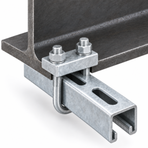
| Modular strut or beam support | Allows field-adjustable positioning with standardized framing components | A rail or frame system is already part of the installation | Rail size, channel nuts, bracket compatibility and system rating |
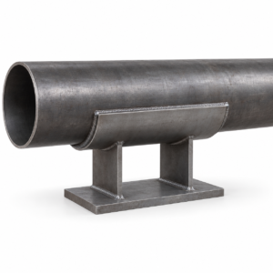
| Floor stanchion with saddle and U-bolt | Transfers load to the floor or foundation and can establish support elevation | Floor space and a suitable base connection are available | Base plate, height, foundation, saddle geometry and anchors |
| Pipe shoe | Provides a defined structural and sliding interface beneath the pipe | Elevation, insulation continuity, movement or heavy load requires a pipe-mounted component | Pipe attachment, shoe height, base interface, loads and temperature |
For adjacent configurations, review YOUNGLEE’s strut beam clamp with U-bolt, pipe saddle support with U-bolt for floor stanchions, and MSS SP-58 Type 24 U-bolt. These pages describe different attachment and load paths; they should not be treated as interchangeable hardware.
Applicable Standards and Their Limits
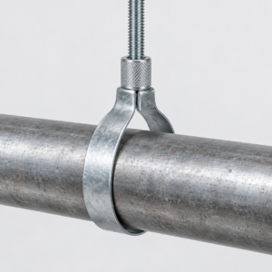
ANSI/MSS SP-58-2025 provides an industry framework for pipe hangers and supports, including materials, design, manufacture, selection, application, inspection and installation. Type 24 identifies a U-bolt product form, while Type 33 is associated in industry catalogs with a heavy welded steel wall bracket. Combining these concepts does not automatically make a custom assembly certified or give it a catalog load rating. The contract must identify the adopted edition, support detail and acceptance requirements.
ASTM A36/A36M may govern selected carbon-steel shapes, plates and bars. ASTM A123/A123M or ISO 1461 can govern batch hot-dip-galvanized fabricated iron and steel articles when specified. Fasteners and threaded hardware may require a different material or coating standard. Anchor selection is especially project-specific: mechanical, adhesive, cast-in or through-bolt connections depend on the substrate, edge distance, embedment, installation method and governing structural design. YOUNGLEE will not infer an anchor capacity from pipe size.
Manufacturing and Inspection Considerations
Fabrication should begin from an approved drawing that separates bracket, U-bolt, hardware and wall-connection requirements. Cutting and drilling establish the arm, wall plate, gussets and U-bolt holes before welding. Weld sequence and fixturing should control distortion so the arm remains square to the wall plate and the U-bolt holes align with the pipe centerline. Galvanized designs need suitable venting, drainage and allowance for coating buildup.
Inspection can include material identification, section and plate dimensions, wall-plate hole pattern, arm projection, pipe centerline offset, gusset location, weld size and appearance, U-bolt rod diameter, inside width, leg length, thread length, nut engagement, assembly fit and coating condition. A dimensional or trial-fit inspection does not establish structural capacity. Any proof test, weld examination, coating-thickness inspection or anchor qualification must be stated in the purchase specification.
Information Required for Quotation
- Actual pipe OD plus NPS or DN, pipe material, wall or schedule where relevant, coating, contents and quantity.
- Bare or insulated condition; for insulation, provide every layer, finished OD, jacket, insert, shield and allowable contact detail.
- Wall-to-pipe centerline, support elevation, available bracket envelope, pipe orientation and installation access.
- Operating, test, occasional, axial, lateral, uplift and vibration loads, plus intended thermal movement.
- Grip, hold-down or guide function, required clearances, tightening method and any stop-nut or spacer arrangement.
- Bracket profile, material, arm length, wall plate, gussets, weld details, U-bolt geometry, thread and hardware.
- Wall or structural substrate, anchor type or through-bolt arrangement, hole pattern, back plate and edge distances.
- Finish or coating system, environment, inspection, documentation, marking, packing and applicable standards.
Frequently Asked Questions
Can the U-bolt be tightened directly onto the pipe?
Only when the approved design calls for a grip or fixed restraint and the pipe, coating, local stress and support reactions have been checked. Guide and hold-down arrangements normally need defined clearance or controlled tightening.
Is nominal pipe size enough to order the bracket?
No. Confirm actual pipe OD, and use the finished insulated OD when the U-bolt is outside insulation. The bracket also needs the wall offset, loads, movement and anchor interface.
Are wall anchors included?
They can be supplied where specified, but their type, material, size and capacity must match the wall or structural substrate and the engineered reactions. A generic anchor should not be selected from pipe size alone.
Can the assembly be hot-dip galvanized?
Yes, subject to material, fabrication and coating review. The project must distinguish the fabricated bracket coating from the coating required on threaded hardware and must allow for drainage, distortion and thread buildup.
Does the bracket have a standard load rating?
Not as a custom product family. Capacity depends on arm projection and section, plate and gusset geometry, welds, material, anchors, substrate, pipe contact, load direction and service condition. Final design values require the project drawing and engineering review.
Request a Custom Wall-Bracket Quotation
Send YOUNGLEE the pipe schedule or actual OD, support drawing, wall-to-pipe centerline, bracket envelope, load cases, movement, wall construction, anchor detail, U-bolt dimensions, material, coating, quantity and inspection requirements. YOUNGLEE can manufacture wall-mounted U-bolt pipe support brackets to approved drawings, samples, applicable standards or confirmed installation conditions. Final geometry, hardware and finish are supplied after technical review of the complete load path and support interface.