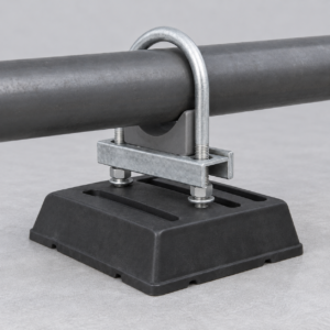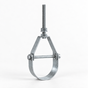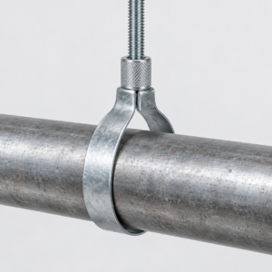
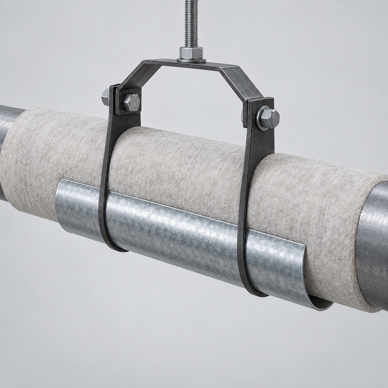
A pipe insulation protection shield for hangers is a formed metal half-cylinder installed outside the insulation and between the insulated pipe and its hanger or support. YOUNGLEE supplies drawing-controlled shields that spread the hanger reaction over a longer contact area, helping reduce local crushing, indentation, and jacket damage in insulated process, utility, HVAC, chilled-water, and steam piping. Galvanized carbon steel is a common starting point; stainless steel and custom sheet, length, diameter, locating-tab, and finish options can be reviewed for the service environment. Final sizing must use the pipe outside diameter, insulation thickness, finished insulated diameter, insulation compressive data, hanger type, load, temperature, movement, vapor-retarder details, and project support specification.
Image note: the featured image is a generated representative configuration showing a galvanized shield between insulated pipe and a clevis hanger. It illustrates the load-spreading arrangement only; it does not verify a project dimension, material grade, coating designation, load rating, insulation system, test, certification, or previous supply.
Pipe Insulation Protection Shield at a Glance
| Selection item | Typical custom supply basis | Information for Buyer Confirmation |
|---|---|---|
| Product type | Formed half-round sheet-metal shield for insulated pipe at a hanger or support point | Support detail, shield function, approved drawing, and quantity |
| Primary function | Distribute the support reaction over a wider axial and circumferential area and protect the insulation jacket | Operating, test, occasional, uplift, lateral, and movement loads |
| Pipe and insulation basis | Manufactured to the finished insulated outside diameter, not to nominal pipe size alone | Actual pipe OD, NPS or DN, insulation thickness, jacket thickness, tolerances, and ovality |
| Shield geometry | Approximately 180-degree curved shield; length, thickness, edge form, and optional locating tabs are drawing-controlled | Required inside diameter, axial length, sheet thickness or gauge, arc, tabs, holes, and edge treatment |
| Materials | Pre-galvanized carbon-steel sheet; 304/304L or 316/316L stainless-steel sheet where technically suitable | Material specification, grade, coating designation, surface finish, and traceability |
| Insulation interface | Foam, fiberglass, mineral-fiber, cellular-glass, calcium-silicate, or another approved system, sometimes with a load-bearing insert | Insulation manufacturer, density, compressive data, temperature, vapor retarder, and jacket construction |
| Compatible supports | Clevis hangers, band hangers, trapeze or strut supports, rollers, and drawing-defined saddles | Support type, bearing width, contact shape, movement direction, and installation access |
| Reference framework | ANSI/MSS SP-58 may apply when named by the contract; ASTM material standards may govern selected sheet products | Applicable edition, project additions, acceptance criteria, inspection, and documentation |
| Customization | Production to buyer drawing, support schedule, sample, or confirmed installation data | Marking, packaging, inspection plan, and matching support components |
Customization Note: The dimensions and technical values listed above are for selection and quotation reference. Actual shield dimensions vary with the applicable standard, actual pipe outside diameter, insulation thickness and compressive behavior, finished insulated diameter, hanger geometry, movement, load, installation arrangement, and project requirements. YOUNGLEE can manufacture pipe insulation protection shields according to customer drawings, specifications, samples, or confirmed installation conditions. Buyers may specify material, sheet thickness or gauge, inside diameter, arc, axial length, edge form, tabs, holes, coating, finish, and other requirements subject to technical review.
What Problem Does an Insulation Protection Shield Solve?
A narrow hanger strap can apply a concentrated reaction to a comparatively soft insulation system. Without an appropriate load-spreading component, the insulation may compress, the outer jacket may crease, or a vapor retarder may be damaged. A correctly sized shield increases the bearing area beneath the insulated pipe and presents a smooth metal surface to the hanger. The shield therefore protects the insulation assembly; it does not strengthen the carrier pipe and does not by itself establish the allowable support load.
The complete load path remains important. Pipe and contents create the vertical reaction, the insulation and any load-bearing insert transfer that reaction to the shield, the shield transfers it to the hanger or support, and the hanger passes it into the supporting structure. If the insulation cannot carry the calculated bearing stress, a longer shield alone may be insufficient. The piping and insulation designer may need a high-density insert, pipe covering protection saddle, insulated pipe shoe, or another engineered support detail.
Construction and Working Principle
The basic shield is formed from sheet into a smooth semicircular profile that matches the outside of the completed insulation system. Its axial length is normally much greater than the width of the hanger strap. That geometry spreads force along the pipe axis and around the lower circumference instead of leaving the insulation to bear on a narrow line.
Plain shield or shield with locating tabs
A plain shield is a simple formed shell. Optional tabs, lips, or small locating features can help center the shield on a hanger and reduce movement during installation. These features must not be treated as an anchor or positive pipe restraint unless the approved support design assigns and verifies that function. Tab geometry also needs clearance from the vapor retarder, jacket seams, and hanger edges.
Shield and high-density insert
A metal shield protects the outer insulation surface and distributes contact; a high-density insert is used when the insulation at the support point needs greater compressive strength. Some systems need both. The insert material, length, vapor sealing, thermal conductivity, temperature capability, and compatibility with the adjoining insulation must come from the insulation-system design. YOUNGLEE should not infer these properties from pipe size alone.
How Should the Shield Be Sized?
Start with the finished insulated outside diameter. For a concentric system, the basic geometric input is the actual pipe OD plus twice the nominal insulation thickness, plus the jacket or other layers where they affect fit. Tolerances, seams, overlaps, field-applied mastics, and insulation ovality can change the required shield inside diameter. A nominal pipe designation such as NPS 4 or DN 100 does not by itself define the finished outside diameter.
Shield length and sheet thickness are then selected from the support reaction, insulation compressive behavior, hanger contact width, allowable local deformation, and project specification. Longer is not automatically better: excessive length can interfere with elbows, branches, jacket joints, heat-tracing details, or movement. Sheet thickness must provide useful stiffness without creating sharp edges or an impractical forming radius.
| Dimension or input | Why it matters | Information for Buyer Confirmation |
|---|---|---|
| Actual pipe OD | Establishes the carrier-pipe geometry beneath the insulation | OD, NPS or DN, wall or schedule where relevant, and tolerance |
| Insulation thickness | Controls the finished support diameter and heat-flow design | Thickness for each layer and whether thickness changes at the support |
| Jacket and vapor retarder | Affects fit, sealing, abrasion risk, and installation sequence | Material, thickness, seam position, overlap, and repair procedure |
| Shield inside diameter | Must fit the completed insulation without destructive point loading | Finished insulated OD, clearance policy, and dimensional tolerance |
| Axial length | Controls bearing area and interaction with adjacent insulation details | Calculated or specified length and available installation envelope |
| Sheet thickness or gauge | Controls stiffness, edge behavior, forming, and handling | Minimum thickness, permitted gauge convention, and material grade |
| Support reaction | Required to check insulation bearing and shield suitability | Operating, hydrotest, occasional, uplift, lateral, and movement cases |
| Hanger interface | Sets the contact width and support geometry beneath the shield | Clevis, band, strut, trapeze, roller, or other support drawing |
Published industry catalogs illustrate why a project-specific selection is necessary. One established protection-shield series uses a 12 in (304.8 mm) axial length for listed configurations, while another public series covers nominal pipe sizes from 1/2 in (12.7 mm) through 24 in (609.6 mm) with listed insulation thicknesses of 1/2 in (12.7 mm), 3/4 in (19.05 mm), 1 in (25.4 mm), 1 1/2 in (38.1 mm), and 2 in (50.8 mm). These are industry-reference examples, not a universal YOUNGLEE size table or a promised project rating. Buyer-supplied inch dimensions are preserved exactly as stated and converted by multiplying the original inch value by exactly 25.4; no rounded inch intermediate is used.
Material and Finish Selection
| Option | Typical selection reason | Important limitation | Information for Buyer Confirmation |
|---|---|---|---|
| Pre-galvanized carbon-steel sheet | Common indoor and general industrial starting point with a factory-applied zinc-coated sheet surface | Cut edges, forming, condensation, chemical exposure, and project corrosion class still require review | ASTM A653/A653M designation if required, coating designation such as G90 or Z275, base-metal grade, and finish |
| Hot-dip galvanized after fabrication | May be considered where a fabricated part needs a different galvanizing route | Not interchangeable with pre-galvanized sheet; drainage, distortion, coating buildup, and edge details differ | Applicable galvanizing specification, coating requirements, dimensions after coating, and acceptance criteria |
| 304/304L stainless steel | General corrosion resistance and a clean metal surface where carbon-steel zinc coating is not preferred | Suitability depends on chlorides, cleaning chemicals, temperature, and contact materials | ASTM A240/A240M grade if specified, finish, thickness, fabrication, and documentation |
| 316/316L stainless steel | Often reviewed for more demanding moisture or chloride exposure | Does not guarantee immunity to pitting, crevice corrosion, or corrosion under insulation | Environment, chloride level, washdown, insulation chemistry, finish, and inspection plan |
ASTM A653/A653M governs zinc-coated or zinc-iron-alloy-coated steel sheet and requires the coating designation to be stated when relevant. It does not rate the completed shield-and-hanger assembly. ASTM A240/A240M covers stainless-steel plate, sheet, and strip for pressure-vessel and general applications; it does not establish insulation compressive strength, support spacing, or the load capacity of the installed shield.
Hot, Cold, and Moisture-Sensitive Service
Cold and chilled-water lines
Cold service makes vapor-retarder continuity especially important. The support detail should avoid puncturing or leaving an unsealed discontinuity that permits moist air to reach a cold surface. The designer should define whether the shield is outside the jacket, whether a high-density insert interrupts the insulation, and how seams and penetrations are sealed. A metal shield is not a vapor barrier and cannot correct an incomplete insulation-system detail.
Hot and steam lines
For hot service, confirm the temperature at the shield and hanger interface, the insulation type, thermal expansion, jacket compatibility, and whether a heavier pipe covering protection saddle is required. The carrier-pipe operating temperature is not necessarily the metal temperature at the outside of the insulation. Selection must use the complete thermal design rather than a generic maximum-temperature statement.
Outdoor and corrosive environments
Outdoor supports require attention to water shedding, jacket seams, crevices, coating damage, dissimilar-metal contact, and inspection access. Stainless steel may be useful in some environments, but grade selection must follow the actual chloride, chemical, temperature, and maintenance conditions. The shield should not trap water against a damaged jacket.
Shield, Protection Saddle, or Pipe Shoe?
| Support component | Main role | Use when | Information for Buyer Confirmation |
|---|---|---|---|
| Insulation protection shield | Spread hanger contact and protect the outside of insulation | The insulation system can transfer the reaction with the specified shield or insert arrangement | Insulation compressive design, shield length, hanger width, and vapor detail |
| Pipe covering protection saddle | Provide a heavier formed bearing member around insulated pipe | Temperature, size, load, or support geometry requires a more substantial saddle | Saddle material, arc, length, thickness, ribs, insulation, and movement |
| High-density insert plus shield | Carry concentrated reaction through stronger insulation at the support point | Ordinary insulation lacks the required compressive performance | Insert material, density, length, thermal properties, vapor sealing, and calculated bearing |
| Insulated or non-insulated pipe shoe | Establish a defined support height and structural load path | The design needs elevation, sliding surface, insulation continuity, or a fabricated structural interface | BOP height, shoe construction, attachment, loads, movement, insulation, and base interface |
For related support architectures, compare YOUNGLEE’s adjustable clevis pipe hanger, the three-bolt pipe clamp for insulated piping, and the adjustable steel pipe roller stand. Each transfers load differently, so the shield must be coordinated with the selected hanger or support rather than chosen in isolation.
Applicable Standards and Specification Boundaries
ANSI/MSS SP-58-2025 provides an industry framework for pipe hangers and supports, including materials, design, manufacture, selection, application, inspection, installation, drawings, marking, and load ratings. It applies only when the project adopts the relevant edition and requirements. A catalog statement that a particular manufacturer’s item corresponds to an MSS type does not automatically certify a custom YOUNGLEE shield or establish its capacity.
The insulation manufacturer, piping specification, project support standard, and approved support drawing remain controlling for insulation compression, vapor sealing, temperature, movement, and spacing. Final documentation may include material certificates, dimensional inspection, coating records, identification, packing lists, or other items agreed during technical review.
Manufacturing and Inspection Considerations
Manufacturing begins with confirmed sheet material and a developed blank sized for the required arc and axial length. Forming should produce a continuous radius without sharp kinks. Edges and corners should be deburred because they may contact a jacket or be handled during insulation work. Where tabs, holes, ribs, or special edges are specified, their position and forming sequence should follow the approved drawing.
Inspection can include material and coating identification, sheet thickness, shield inside diameter, arc profile, axial length, edge condition, tab location, surface condition, and trial fit to a gauge or approved sample. Packaging should prevent nested shields from scratching or locking together and should protect formed edges during export handling. Load testing or assembly qualification is project-specific and must not be assumed from dimensional inspection alone.
Information Required for Quotation
- Actual pipe OD plus NPS or DN, pipe material, wall or schedule where relevant, and operating/test condition.
- Insulation type, manufacturer or specification, thickness of every layer, density or compressive data, operating temperature, vapor retarder, and outer jacket.
- Finished insulated outside diameter, tolerances, jacket seams, and any field-applied coating or mastic that affects fit.
- Hanger or support type, contact width, support drawing, axial movement, lateral behavior, and installation orientation.
- Shield material, sheet thickness or gauge, inside diameter, arc, axial length, edge form, tabs, holes, coating, and finish.
- Operating, test, occasional, uplift, and lateral loads; support spacing; quantity; governing standard; inspection; marking; and documentation.
Frequently Asked Questions
Is the shield sized from nominal pipe size?
No. Nominal size is useful identification, but the shield must fit the completed insulation system. Confirm actual pipe OD, insulation thickness, jacket construction, and the finished insulated diameter.
Does a metal shield eliminate the need for a high-density insert?
Not necessarily. The shield spreads contact at the hanger, while the insulation or insert must still carry the reaction. The insulation designer determines whether an insert is required from compressive strength, temperature, load, and deformation limits.
Can the shield be used with a clevis hanger or strut trapeze?
Yes, both are common installation concepts, provided the shield curvature, length, sheet thickness, and locating details are coordinated with the actual hanger or strut geometry and the insulation system.
Should galvanized or stainless steel be selected?
Selection depends on moisture, chlorides, chemicals, temperature, jacket material, dissimilar-metal contact, inspection access, and the project corrosion specification. Neither option is universally superior.
Does the shield have a universal load rating?
No. Suitability depends on the complete load path, shield geometry and material, insulation or insert compressive behavior, hanger contact, pipe operating condition, and supporting structure. Final values require project review.
Request a Custom Shield Quotation
Send YOUNGLEE the pipe and insulation schedule, finished insulated diameter, hanger or support drawing, loads, temperature, movement, shield dimensions, material and finish, quantity, and required inspection documents. YOUNGLEE can manufacture pipe insulation protection shields to approved drawings, samples, applicable project standards, or confirmed installation conditions. Final geometry and material selection are supplied after technical review of the complete support and insulation interface.