A U-bolt pipe shoe is a mechanically attached support assembly that uses two or more U-bolts to retain a horizontal pipe on a fabricated steel shoe without welding the shoe directly to the carrier pipe. The U-bolts pass around the pipe and through the shoe flanges, while the shoe establishes the bottom-of-pipe elevation and transfers vertical reaction into a beam, rack, slide plate, or other engineered support surface. YOUNGLEE manufactures custom U-bolt-on pipe shoes in carbon steel or project-specified stainless steel to approved drawings. Pipe outside diameter, support height, shoe length, loads, movement function, U-bolt geometry, materials, coating, contact protection, and inspection requirements are customized. Final capacity and suitability depend on the complete piping-support design, not on appearance or nominal pipe size alone.
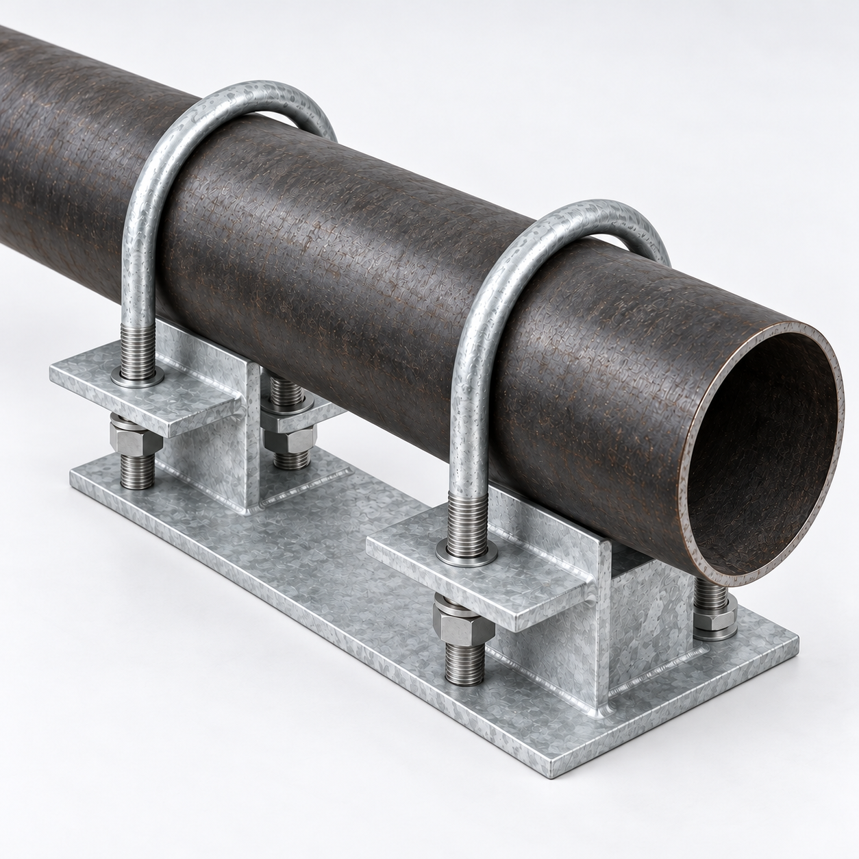
Image note: the featured visual is a generated representative of a generic twin-U-bolt pipe shoe. It illustrates the assembly concept only and does not verify project dimensions, material grade, coating process, load rating, temperature, movement function, certification, testing, or previous supply.
U-Bolt Pipe Shoe Product at a Glance
| Selection item | Typical custom supply basis | Information for Buyer Confirmation |
|---|---|---|
| Product type | Fabricated steel pipe shoe retained to a horizontal pipe by two or more round-bend U-bolts | Approved support drawing, assembly arrangement, quantity of U-bolts, and revision |
| Primary function | Carry vertical reaction at a specified bottom-of-pipe elevation without welding the shoe to the carrier pipe | Vertical, lateral, axial, uplift, friction, thermal, occasional, and installation loads |
| Pipe interface | Direct metal contact or drawing-defined wear pad, liner, isolation layer, or curved bearing plate | Actual pipe OD, pipe material, coating, wall or schedule where relevant, contact-pressure limits, and compatibility |
| Shoe construction | Split-beam, channel, plate-and-web, or other fabricated profile with a flat lower bearing surface | BOP height, shoe length and width, web spacing, plate thickness, end plates, gussets, slots, and clearances |
| U-bolt system | Round-bend carbon-steel, stainless-steel, or alloy-steel U-bolts with matching nuts and washers | Rod diameter, inside width, bend radius, leg length, thread, thread length, material grade, coating, and tightening basis |
| Materials | Carbon steel or project-specified stainless steel, subject to fabrication and compatibility review | Applicable material specifications, grades, product forms, traceability, toughness, and temperature basis |
| Surface protection | Plain, painted, hot-dip galvanized, electroplated, or project coating where technically suitable | Coating standard, class or thickness, preparation, masking, thread allowance, repair, color, and inspection |
| Supply basis | Manufactured to approved drawing, support schedule, sample, or agreed dimensional specification | Applicable standard, calculations, inspection plan, documentation, marking, packaging, and acceptance criteria |
Customization Note: This table is a procurement framework, not a stock size series or certified capacity schedule. Final geometry, sections, welds within the shoe, U-bolt preload, materials, coatings, movement function, and allowable reactions require an approved project design.
What Is a U-Bolt-On Pipe Shoe?
A U-bolt-on pipe shoe combines a fabricated load-carrying shoe with separate bent-bolt retainers. The pipe rests on the upper bearing portions of the shoe, and the U-bolts wrap over the pipe at separated locations. Their threaded legs pass through flanges or lugs in the shoe and are secured with nuts and washers. The shoe then bears on structural steel or on a project-defined sliding interface. Industry catalogs also use terms such as U-bolt pipe shoe, U-bolt-on pipe shoe, and pipe shoe with U-bolts. These terms describe one product family; they should not be treated as unrelated products.
How does the load path work?
The intended vertical reaction begins at the pipe-to-shoe bearing interface, enters the shoe webs or beam section, crosses the lower bearing surface, and finishes at the support steel. The U-bolts keep the pipe and shoe assembled and may contribute to uplift or lateral restraint only when the design explicitly assigns those functions. Pipe local stress, contact width, shoe-web strength, base bending, U-bolt bending and tension, holes, washers, nuts, supporting-steel bearing, and any slide plate can each govern the completed support. A visually heavy assembly therefore does not create an automatic safe working load.
Why use a mechanical attachment?
A mechanically attached shoe may be selected when project rules discourage or prohibit field welding to the carrier pipe, when the support must be removable, or when the pipe metallurgy and welding controls make a bolted interface preferable. This does not make the assembly universally suitable for non-welded service. The designer must still address local pipe contact, coating damage, differential movement, U-bolt tightening, vibration, cyclic effects, corrosion traps, galvanic compatibility, and inspection access.
Information for Buyer Confirmation
| Dimension or input | Why it matters | Information for Buyer Confirmation |
|---|---|---|
| Actual pipe outside diameter | Controls the U-bolt inside width, bend fit, bearing profile, and assembly clearance | State actual OD and tolerance; do not substitute NPS or DN alone |
| BOP support height | Sets the bottom-of-pipe elevation above the support surface and influences shoe stability | State required installed height, tolerances, shims, grout, and support-steel datum |
| Shoe length | Affects bearing area, web spacing, U-bolt spacing, and load distribution | State total length, allowable envelope, end clearances, and any insulation-band slots |
| Shoe width and lower bearing face | Must fit the support beam or slide plate and distribute the reaction | State supporting-steel width, slide plate size, guide gaps, and edge-clearance requirements |
| U-bolt rod and thread | Controls hole size, nut engagement, tightening, and coating allowance | State rod diameter, metric or inch thread, pitch or TPI, class or fit, thread length, nuts, and washers |
| U-bolt spacing | Changes load sharing, shoe stability, and installation access | State center-to-center spacing or provide the approved drawing |
| Pipe contact system | Influences pressure, friction, coating protection, drainage, and galvanic behavior | State bare contact, wear plate, pad, liner, sleeve, isolation washer, and required material |
| Movement and restraint | Determines whether the shoe slides, guides, holds down, grips, or anchors | State permitted travel, guide gaps, friction basis, uplift, restraint directions, and design reactions |
| Installation envelope | Nuts and tools need access below or beside the flanges | State obstructions, erection sequence, torque access, removable components, and maintenance space |
Customization Note: Dimensions are made to the approved drawing. If a drawing gives a decimal inch value, retain every supplied decimal place before any conversion; multiply the exact inch value by 25.4 to obtain millimetres, then apply only the drawing-defined reporting tolerance. Nominal pipe size must never be converted as though it were the actual outside diameter.
Why Actual Pipe OD and BOP Height Control Selection
Nominal pipe size identifies a piping family; it is not the manufacturing diameter for a fitted U-bolt. The buyer should provide the actual finished outside diameter, including any coating, jacket, pad, or other layer located inside the U-bolt. YOUNGLEE uses that dimension with the required clearance or grip condition to define the inside width and bend geometry. An unverified nominal designation can produce insufficient clearance, excessive gap, point contact, damaged coating, or an incorrect restraint condition.
Bottom-of-pipe height is equally important. A taller shoe changes the load path and can increase web bending, lateral flexibility, and overturning demand. A lower shoe may create interference between the U-bolt legs, nuts, lower bearing surface, and support steel. Published supplier drawings sometimes show their own standard heights and lengths, but those values are proprietary product configurations rather than universal dimensions. YOUNGLEE treats BOP height, length, member section, U-bolt spacing, and reinforcement as project inputs.
Should the U-bolts grip the pipe?
Not automatically. Some assemblies are detailed as positive hold-downs, while others retain the pipe on the shoe without deliberately applying high clamping force. If thermal movement is expected at the support, uncontrolled tightening can raise friction, damage a coating or liner, or create an unintended restraint. The buyer must specify whether the support is sliding, guided, held down, gripping, or anchoring and provide the calculation or tightening basis for that behavior.
Fabricated Shoe Construction and U-Bolt Geometry
The shoe can be fabricated from structural shapes, plate-and-web construction, or another drawing-defined section. Typical details include a flat lower bearing surface, two vertical webs or uprights, top flanges or lugs for U-bolt holes, and optional end plates, gussets, insulation-band slots, drainage details, or guide interfaces. Welds within the shoe must be sized and inspected for the assigned reactions. These fabrication welds are different from welding the shoe to the carrier pipe; the defining feature of this product is that the pipe-to-shoe connection is mechanical.
ASME B18.31.5 establishes general requirements for inch-series bent bolts and may be referenced when it matches the order. It does not define the complete pipe shoe, material selection, coating, load capacity, or project restraint function. The approved drawing must still specify the U-bolt form, rod size, inside dimensions, bend radius, tangent length, thread, thread length, nuts, washers, material, heat treatment where applicable, coating, inspection, and dimensional tolerance.
Why two separated U-bolts are useful
Two longitudinally separated U-bolts provide a stable mechanical connection between the pipe and the longer shoe. Their spacing helps control relative rotation and distributes retention forces along the assembly. That benefit depends on accurate fabrication and installation. Unequal tightening, misaligned holes, poor pipe fit, or a distorted shoe can transfer load unevenly. More U-bolts may be specified for long or high-reaction assemblies, but quantity alone is not proof of capacity.
Material and Surface-Finish Options
| Component or condition | Possible project option | Selection point |
|---|---|---|
| Fabricated shoe | Carbon steel or project-specified stainless steel | Confirm structural grade, product form, weldability, toughness, temperature, corrosion allowance, and traceability |
| U-bolts | Carbon steel, stainless steel, or alloy steel when technically justified | Specify a material standard and grade separately from the shoe; do not infer U-bolt strength from shoe material |
| Nuts and washers | Compatible carbon-steel, alloy-steel, or stainless hardware | Coordinate thread, mechanical properties, coating, galling control, and galvanic compatibility |
| Hot-dip galvanizing | Fabricated steel and fasteners galvanized to applicable, separately identified specifications | Confirm venting, drainage, distortion risk, coating thickness, thread allowance, nut oversize, finish, and repair |
| Electroplated finish | Zinc or another approved fastener coating | Confirm ISO 4042 or another specified system, coating designation, thread fit, friction, embrittlement risk, and corrosion exposure |
| Paint or project coating | Primer, multi-coat system, or other approved protection | State surface preparation, dry-film thickness, cure, color, masked interfaces, field repair, and compatibility |
| Contact protection | Wear pad, thin liner, isolating washer, sleeve, or project-defined barrier | Confirm material identity, thickness, temperature, compressive behavior, wear, chemical exposure, drainage, and replacement |
Customization Note: Material and finish names are not interchangeable performance guarantees. The buyer must define the governing specifications, grades, coating designations, service environment, temperature, compatibility, inspection, and documentation for every component in the assembly.
How should galvanizing be specified?
Hot-dip galvanizing of a fabricated shoe and galvanizing of threaded fasteners are related but not identical procurement tasks. ASTM F2329/F2329M addresses hot-dip zinc coating on carbon- and alloy-steel fasteners, while the fabricated structural component may require a different applicable coating specification. Thread allowance, nut fit, drainage and vent holes, masking, distortion, coating repair, and contact surfaces must be resolved on the drawing and purchase specification. A generic request for “HDG” is not enough for a coordinated assembly.
U-Bolt Pipe Shoe Compared with Other Supports
| Support arrangement | Pipe attachment | Key selection difference |
|---|---|---|
| U-bolt-on pipe shoe | Two or more U-bolts mechanically retain the pipe to a fabricated shoe | Removable pipe attachment, defined BOP elevation, continuous lower bearing face, U-bolt spacing, and tightening basis |
| Welded pipe shoe | Shoe or wear plate is welded to the carrier pipe | Requires parent-pipe weldability, welding procedure, local-stress review, NDE, and owner approval |
| Single U-bolt saddle support | One U-bolt retains the pipe on a curved saddle head or stanchion | Compact point support with a different shank or pedestal load path and generally shorter longitudinal footprint |
| Plain U-bolt on structural steel | U-bolt passes around the pipe and through a beam, plate, or bracket | No elevated shoe body or continuous fabricated lower bearing member unless separately added |
| Guide or hold-down clamp | Clamp or U-bolt controls selected movement or uplift at a support | Guide gaps, clearances, friction, and restraint reactions govern; vertical support may come from another component |
Customization Note: The support name does not define its engineering function. The piping-support drawing must state whether the assembly supports, slides, guides, holds down, grips, anchors, or combines functions, and must provide the corresponding reactions and movement cases.
For a directly welded alternative, review YOUNGLEE’s welded pipe shoe with wear plate. For a compact single-point bearing arrangement, compare the pipe saddle support with U-bolt. When only the bent fastener is required, the zinc-plated U-bolt pipe clamp page explains coating and hardware inputs for a standalone U-bolt.
Movement, Sliding, Guiding, and Restraint
A U-bolt pipe shoe can sit on bare structural steel, a stainless-steel plate, PTFE-based slide material, graphite, or another engineered bearing system, but the lower interface must be selected separately. Low-friction materials do not remove the need to calculate friction force, edge pressure, travel, temperature effects, environmental exposure, and replacement access. The shoe may also run between guide angles or against stops. Guide gaps must account for installation tolerance, thermal travel, lateral displacement, coating thickness, and fabrication tolerance.
If the design requires uplift restraint, lateral restraint, or an anchor function, the reactions must be stated explicitly. The U-bolts, shoe, holes, welds within the shoe, guide steel, support beam, and connections all require evaluation. YOUNGLEE does not infer anchor capacity from a product photograph or from the number of fasteners.
Installation and Engineering Review
Check the assembled pipe condition
Verify actual pipe OD, ovality, coating, insulation interfaces, weld seams, and local projections before tightening. The shoe must sit squarely on its support surface without forcing the pipe or U-bolts into alignment. Contact pads or liners must be continuous, correctly located, and free of trapped debris.
Use a defined tightening method
Torque is not a universal proxy for clamping force. Thread condition, coating, lubrication, nut system, prevailing torque, washer bearing, and installation sequence affect the result. Use the project-approved procedure and tighten the U-bolts evenly so the shoe remains centered. Do not draw a distorted shoe into place by over-tightening one leg.
Preserve movement and access
After installation, confirm specified guide gaps, slide travel, nut clearance, thread engagement, tool access, coating condition, and drainage. The pipe must not be unintentionally locked against a guide or stop. If the support is removable, the maintenance plan should allow nut removal and shoe extraction without cutting the carrier pipe.
Inspect the complete load path
Inspection should cover dimensions, material identity, fabrication welds, hole position, U-bolt fit, threads, nuts, washers, coating, contact protection, marking, and documentation. Project requirements may add magnetic-particle, liquid-penetrant, ultrasonic, coating-thickness, dimensional, or load-related verification. The method and acceptance criteria must be stated before manufacture.
Standards and Reference Framework
ANSI/MSS SP-58-2025 provides an industry framework for the materials, design, manufacture, selection, application, inspection, and installation of pipe hangers and supports. ASME B18.31.5-2011 (R2021) provides general requirements for inch-series bent bolts. ASTM F2329/F2329M-15(2023) addresses hot-dip zinc coating for carbon- and alloy-steel threaded fasteners, and ISO 4042:2022 addresses electroplated coating systems for fasteners. These references govern different parts of the procurement package. None, by itself, defines the complete custom shoe, its load rating, the supported pipe, or the installed structure.
The order should identify the applicable edition, scope, project additions, material specifications, design basis, drawing hierarchy, inspection, documentation, and acceptance criteria. Where requirements conflict, the buyer and manufacturer must resolve them before production.
Generated Representative Product Image
The featured image was generated as an unbranded representative visual. It shows one dark horizontal steel pipe, one galvanized fabricated shoe with a continuous lower bearing plate and structural webs, and two longitudinally separated round U-bolts with four threaded legs, washers, and nuts. It is not an exact drawing, certified configuration, supplier-specific catalog model, or evidence of a completed project. Hole arrangement, flange geometry, member section, U-bolt fit, hardware position, dimensions, materials, coatings, loads, and movement function must follow the approved quotation and drawing.
Frequently Asked Questions
Is a U-bolt pipe shoe the same as a clamp-on pipe shoe?
They are related non-welded support families, but the attachment hardware can differ. A U-bolt-on shoe specifically uses bent U-bolts around the pipe; a clamp-on shoe may use split bands or fabricated clamps with closure bolts. The approved drawing determines the exact product.
Can the shoe be used as a sliding support?
Yes, when the lower bearing interface, friction basis, travel, guide gaps, temperature, and structural reactions are engineered for sliding service. A flat shoe surface alone does not establish safe movement behavior.
Does the assembly eliminate welding?
It eliminates welding between the shoe and carrier pipe when manufactured and installed as a U-bolt-on design. The shoe itself normally contains fabrication welds, and its supporting structure may have separate welded connections.
Can U-bolts be coated or sleeved?
Yes, subject to the service and drawing. Coating or sleeve material, thickness, coverage, temperature, friction, chemical compatibility, thread allowance, and inspection must be defined. If insulation is specified on the legs, it should meet the first thread without covering the threads or leaving unnecessary exposed unthreaded shank.
What data is needed for a quotation?
Provide the approved drawing or support schedule, actual pipe OD, BOP height, shoe length and width, member section, U-bolt spacing and geometry, thread, materials, coatings, contact system, movement function, all design reactions, temperature, corrosion environment, support-steel interface, quantity, inspection, documentation, and marking requirements.
Request a Quotation from YOUNGLEE
Send YOUNGLEE the pipe-support drawing, actual pipe outside diameter, nominal size for identification, bottom-of-pipe height, shoe length and width, U-bolt rod and thread, inside width, leg and thread lengths, U-bolt spacing, material grades, nuts and washers, coating or isolation system, movement and restraint function, design reactions, operating temperature, corrosion environment, supporting-steel geometry, quantity, inspection plan, and documentation requirements. YOUNGLEE can review custom U-bolt pipe shoes for production to an applicable standard or approved project drawing. Final dimensions, materials, surface treatment, hardware, fabrication details, and acceptance criteria are confirmed during technical review before manufacture.