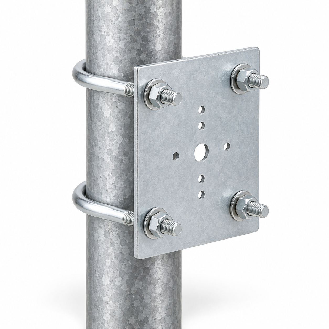
A U-bolt pole mounting bracket is a mechanical assembly that uses two formed U-bolts and a drilled steel plate to attach instruments, enclosures, signs, sensors, or other project equipment to a round vertical pole. YOUNGLEE supplies custom dual U-bolt mounting brackets in carbon steel or stainless steel, with project-selected threads, plate geometry, hole patterns, and corrosion protection. The two U-bolts wrap around the pole at separated elevations, while their four threaded legs pass through the mounting plate and are secured from the front. Pole outside diameter, equipment weight, wind and vibration loads, eccentricity, environment, clearances, and the final equipment interface must be confirmed for each project; dimensions can be produced to an approved drawing.
U-Bolt Pole Mounting Bracket at a Glance
| Product fact | Available project basis | Information for Buyer Confirmation |
|---|---|---|
| Product type | Dual round-bend U-bolts with one drilled or formed equipment mounting plate | Complete assembly drawing, orientation, component count, and intended equipment |
| Primary function | Mechanically attach a project-defined plate or equipment interface to a round pole without welding to the pole | Whether the bracket locates, supports, restrains, or only positions the equipment |
| Common materials | Carbon-steel U-bolts and plate; 304, 304L, 316, or 316L stainless-steel options where technically suitable | Separate material and mechanical-property requirements for U-bolts, plate, nuts, and washers |
| Finish options | Electro-zinc, hot-dip galvanized, zinc-nickel, painted or project coating; stainless steel may be supplied uncoated | Coating standard, system, thickness or class, passivation, sealer, thread allowance, and mating materials |
| Size basis | Custom to actual finished pole outside diameter and the approved plate interface | Pole OD, roundness, taper, seam, coating, plate envelope, offsets, and installation clearance |
| Hardware | Matching nuts and flat washers; locking features only when specified | Thread, nut and washer standards, grades, coating, lubrication, locking method, and tightening procedure |
| Applications | Instrument panels, small enclosures, antennas, cameras, sensors, signs, junction boxes, and custom industrial accessories | Equipment mass, center of gravity, projected area, loads, vibration, service environment, and required approvals |
| Customization | U-bolt rod diameter, inside width, bend radius, leg and thread length, plate size, thickness, hole pattern, edge treatment, and finish | Drawing revision, tolerances, load basis, acceptance method, documentation, quantity, and packaging |
Customization Note: These are configurable supply options, not a universal size series or load rating. Final geometry, materials, coating, hardware, and acceptance requirements must follow the buyer’s approved drawing and engineering review.
What Is a Dual U-Bolt Pole Mounting Bracket?
The assembly converts a round pole into a flat mounting interface. Each round-bend U-bolt passes behind the pole, and both threaded legs project through matching holes in the front plate. Separating the upper and lower U-bolts gives the plate two clamping levels, helping it resist rotation compared with a single narrow connection. The plate then provides project-defined holes or slots for the equipment, a secondary bracket, or an enclosure.
Buyers may use the terms U-bolt pole mounting bracket, dual U-bolt mounting plate, pole mount bracket with U-bolts, instrument pole clamp, or equipment pole mounting kit. These terms describe related procurement intent, but they do not guarantee the same plate, hole pattern, pole range, strength, corrosion system, or equipment compatibility.
What the bracket does not include
Unless the quotation states otherwise, the base assembly does not include the field instrument, electrical enclosure, antenna, camera, sign, pole, cable glands, secondary articulating arm, electrical bonding conductor, structural foundation, or engineering calculations. A representative hole pattern must not be treated as compatibility with a proprietary device.
Why two U-bolts are commonly used
Two vertically separated U-bolts provide four threaded attachment points and a longer resisting couple between the plate and pole. This can improve positional stability, but it does not create an automatic safe working load. Plate bending, U-bolt bending, thread loading, friction, pole ovalization, local coating damage, equipment eccentricity, wind, vibration, and installation torque all remain part of the project assessment.
How Is This Assembly Different from Other U-Bolt Products?
| Assembly | Members connected | Main selection inputs | Important distinction |
|---|---|---|---|
| Dual U-bolt pole mounting bracket | Equipment plate to one round vertical pole | Pole OD, U-bolt spacing, plate and hole pattern, equipment loads, environment | Creates a flat equipment interface on a pole |
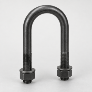
| Standard pipe U-bolt clamp | Process or service pipe to beam, rail, or support surface | Pipe actual OD, grip or guide function, rod diameter, leg length, thread | Retains a pipe rather than carrying a separate equipment plate |
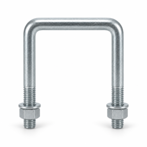
| Square-bend U-bolt | Rectangular tube or section to another member | Finished width and depth, corner radius, wall thickness, clearances | Matches a rectangular member rather than a round pole |
| 90-degree crossover plate kit | Two tubes crossing at right angles | Both tube ODs, crossing angle, plate hole centers, slip or grip requirement | Joins two tubular members instead of mounting equipment to one pole |
| Band-style pole clamp | Equipment rails or brackets to round or square poles | Pole perimeter, band range, tensioning method, edge and coating protection | Uses flexible bands or straps rather than formed U-bolts |
Customization Note: These arrangements are not interchangeable by appearance alone. Confirm the connected members, load path, hole pattern, tightening method, environment, and approved design before choosing the assembly.
How Should the Bracket Be Sized?
Begin with the actual finished outside diameter of the pole at both U-bolt elevations. Nominal pipe size does not equal actual outside diameter, and a tapered, polygonal, seamed, coated, or damaged pole may not behave like a smooth cylindrical tube. Measure coating thickness, out-of-roundness, taper, and any longitudinal seam that could affect contact.
The U-bolt inside width must allow assembly over the finished pole without forcing the legs apart. Excess clearance can reduce positional control and increase local bending, while an undersized U-bolt may damage the pole coating or prevent the plate from seating. The approved drawing should define the bend datum, inside width, inside height, tangent points, rod diameter, leg parallelism, thread length, and tolerances.
Dimensions and Inputs for Custom Manufacture
| Dimension or input | Why it matters | Information for Buyer Confirmation |
|---|---|---|
| Finished pole outside diameter | Controls U-bolt inside width, bend geometry, clearance, and bearing contact | Actual OD at both clamp levels, tolerance, taper, roundness, seam, coating, and pole wall thickness |
| U-bolt rod diameter | Affects forming strain, thread size, plate-hole fit, strength, and required bend radius | Nominal and actual diameter, material, mechanical properties, forming condition, and tolerance |
| Inside width and bend | Determines fit around the pole and the position of the straight legs | Inside width, inside height, bend radius, tangent points, leg parallelism, and datum |
| Leg and thread length | Must accommodate the plate, washers, nuts, coating, runout, and tool access | Overall leg length, usable thread, runout, minimum engagement, and maximum protrusion |
| Vertical U-bolt spacing | Influences plate stability, resisting couple, hole locations, and equipment clearance | Center-to-center spacing, tolerance, datum, and whether the spacing is fixed or slotted |
| Plate envelope and thickness | Affect equipment clearance, stiffness, edge distance, mass, and corrosion protection | Length, width, thickness, bend or flange details, corners, flatness, material, and finish |
| U-bolt holes | Must match the finished legs without forcing them or seating hardware on hole edges | Hole diameter, horizontal and vertical centers, slots if permitted, edge distance, and tolerance |
| Equipment hole pattern | Defines compatibility with the project equipment or secondary bracket | Hole and slot sizes, centers, datums, orientation, countersink or thread details, and keep-out zones |
| Equipment and load inputs | Control plate stiffness, hardware selection, anti-rotation needs, and structural review | Mass, center of gravity, projected area, wind, vibration, impact, maintenance loads, and design factors |
Customization Note: Place all dimensions and datums on one approved assembly drawing. If inch dimensions are supplied, preserve every stated decimal place before multiplying by 25.4; do not round the inch value before conversion.
Material and Corrosion-Protection Selection
| Option | Typical selection reason | Key project checks |
|---|---|---|
| Carbon steel with electro-zinc | Indoor or protected industrial service where a compact plated finish is suitable | Coating system, thickness or class, passivation, sealer, hydrogen-embrittlement controls, thread fit, and expected exposure |
| Carbon steel with hot-dip galvanizing | Outdoor service where a heavier zinc coating is specified | Applicable component standards, coating allowance, plate-hole clearance, nut tapping, drainage, repair, and mating finish |
| Carbon steel with zinc-nickel | Projects specifying a zinc-alloy coating system and controlled friction or corrosion performance | Coating designation, passivation, sealer or topcoat, friction requirement, hydrogen risk, gaugeability, and acceptance tests |
| 304 or 304L stainless steel | General corrosion resistance where the service environment and strength condition are compatible | Exact grade, property basis, forming, galling, nut pairing, lubrication, surface finish, and galvanic contact |
| 316 or 316L stainless steel | More demanding wet or chloride-influenced environments after project review | Chloride level, crevices, temperature, cleaning chemicals, material condition, galling, and dissimilar-metal isolation |
Customization Note: Material and finish names alone do not establish service life, load capacity, or environmental suitability. Specify each component separately and define the complete corrosion system, inspection basis, and mating materials.
Carbon-steel U-bolts and plates
Carbon steel is a practical basis for many custom mounting assemblies, but the purchase order should identify the required chemistry or material standard, mechanical properties, forming condition, thread method, and test basis. The plate and U-bolts may need different material requirements because their forming, bending, bearing, and threading functions differ.
Stainless-steel options
ISO 3506-1:2020 addresses specified stainless-steel grades and property classes for bolts, screws, and studs with ISO metric threads when the standard is applicable to the ordered fasteners. It does not by itself define a custom U-bolt assembly, pole load, plate strength, fatigue resistance, or equipment compatibility. The buyer should state whether ISO 3506-1 or another material and mechanical-property specification applies to the U-bolts and matching nuts.
Plate, nuts, and washers
The plate material, hole finish, flatness, and edge treatment influence both load transfer and coating durability. Nuts and washers require compatible dimensions, grades, coatings, hardness, and bearing surfaces. Do not assume that a stainless U-bolt with carbon-steel hardware, or a galvanized U-bolt with untreated plate holes, forms a complete corrosion-resistant system.
How Should the Coating Be Specified?
Electroplated zinc and zinc-alloy systems
ISO 4042:2022, including Amendment 1:2026 where contractually adopted, specifies electroplated coating systems for steel fasteners and includes measures related to hydrogen-embrittlement risk. ASTM B633-23 covers electrodeposited zinc coatings on iron and steel articles. The drawing should identify the governing standard, system, thickness or class, passivation, sealer or topcoat, appearance, friction or lubrication needs, thread gaugeability, and required documentation.
Hot-dip galvanized assemblies
Hot-dip galvanizing is not interchangeable with electroplating. Its coating build can change U-bolt thread fit, washer seating, plate-hole clearance, and assembly dimensions. Confirm whether parts are galvanized after forming, which fastener and fabricated-item coating standards apply, whether nuts are oversized or retapped, and how cut edges or damaged areas are repaired.
Mixed-metal contact
A stainless bracket on a galvanized or carbon-steel pole can create dissimilar-metal contact, while rainwater trapped behind a flat plate can promote crevice corrosion. The project engineer should decide whether isolating pads, compatible coatings, drainage, sealing, or another detail is needed. Any pad thickness changes the required U-bolt dimensions and tightening response.
Engineering and Installation Review
Define the complete load path
The load path runs from the equipment through its mounting screws, the plate, U-bolt holes, washers, nuts, U-bolt bends, pole wall, pole support, and foundation. Equipment weight is only one input. Wind on the equipment, cable forces, vibration, impact, maintenance access, eccentricity, ice, and thermal movement may produce tension, shear, bending, torsion, fatigue, or slip at different interfaces.
Protect the pole and maintain contact
The two U-bolts should seat consistently around the same pole, and the plate should not rock across weld seams, tapers, raised coatings, or surface damage. Excess tightening can flatten thin-wall tube, bend the plate, damage coatings, or overload threads. Too little tightening can permit rotation or settlement. A project-defined tightening procedure is therefore essential.
Control tightening and thread engagement
Torque depends on thread system, material, coating, lubrication, nut grade, washer hardness, pole stiffness, and required clamp behavior. The approved procedure should define torque or another tightening method, tightening sequence, minimum thread engagement, maximum projection, witness marks, and any recheck after installation. Generic torque tables are not a substitute for assembly-specific review.
Verify equipment clearance and service access
Confirm access for sockets or wrenches at all four nuts, clearance behind the plate, cable bend radius, gland orientation, door swing, display visibility, drainage, bonding, and removal of the equipment without disturbing the pole connection. Do not drill, slot, flame-adjust, or bend finished components in the field unless an approved procedure permits it.
Typical Applications
- Instrument transmitters and analyzers mounted on industrial pipe stands or round poles;
- Small control, junction, or communication enclosures with a project-specific backing plate;
- Cameras, antennas, sensors, beacons, or signs where the supporting pole and loads are engineered;
- Monitoring equipment at water, wastewater, energy, transportation, marine, and process facilities;
- Custom accessory plates for retrofit installations where welding to the pole is restricted.
For a direct pipe-retaining product, compare the zinc-plated U-bolt pipe clamp. Where the member is rectangular rather than round, review a custom square-bend U-bolt. For joining two tubular members at right angles, see the 90-degree pipe crossover plate kit. These assemblies have different load paths and are not interchangeable.
Representative Image Disclosure
The featured image is a newly generated representative product visual. It shows exactly two silver round-bend U-bolts wrapping around one galvanized-style round pole, with four threaded legs passing through one rectangular front plate and secured by four nuts and flat washers. The central plate holes are illustrative only. The image does not establish dimensions, pole range, material or fastener grade, coating specification, equipment compatibility, load rating, certification, previous project supply, or suitability for any installation.
What Should the Buyer Provide for Quotation?
- Complete assembly drawing showing the pole, both U-bolts, plate, equipment interface, orientation, datums, and adjacent clearances;
- Actual finished pole OD at both clamp levels, wall thickness, material, coating, seam, taper, roundness, and structural details;
- U-bolt rod diameter, inside width and height, bend radius, leg length, thread length, thread specification, and tolerances;
- Vertical spacing between U-bolts and horizontal leg center spacing;
- Plate length, width, thickness, bends or flanges, corner treatment, flatness, U-bolt holes, equipment holes, slots, and keep-out zones;
- Material and mechanical-property requirements for U-bolts, plate, nuts, and washers;
- Coating or surface-finish standard, system, thickness or class, passivation, sealer, lubrication, color, repair, and inspection;
- Equipment mass, center of gravity, projected area, wind, vibration, impact, maintenance loads, corrosion environment, and design temperature;
- Tightening method, locking feature, bonding or isolation requirements, installation sequence, acceptance criteria, documentation, quantity, and drawing revision.
Frequently Asked Questions
Is pole diameter the same as nominal pipe size?
No. U-bolt fit must be based on actual finished outside diameter. Nominal pipe size can correspond to a different outside diameter, and poles may also be tapered, seamed, coated, or out of round.
Can one bracket fit both round and square poles?
Not automatically. A round-bend U-bolt is intended around a round member. Square poles generally require bands, formed channels, square-bend U-bolts, or another approved interface that matches the corners and load path.
Does the mounting plate have a universal instrument hole pattern?
No hole pattern is universally compatible. Provide the exact equipment or secondary-bracket drawing, hole and slot dimensions, datums, orientation, edge distances, and keep-out zones.
Can the bracket carry any enclosure shown with the same pole size?
No. Pole size alone does not determine capacity. Equipment mass, center of gravity, projected area, wind, vibration, plate stiffness, U-bolts, pole wall, tightening, support structure, and required design factors must all be reviewed.
Should the nuts be tightened to a standard torque?
Use a project-approved tightening procedure. Torque varies with thread, material, coating, lubrication, hardware grade, washer, pole stiffness, and desired clamp behavior; a generic value may damage the assembly or leave it loose.
Request a Quotation from YOUNGLEE
Send YOUNGLEE the approved pole-mounting drawing, actual pole geometry, U-bolt and plate dimensions, equipment interface, loads, materials, threads, hardware, coating system, tightening and inspection requirements, service environment, documentation, quantity, and applicable standards. YOUNGLEE can review custom dual U-bolt pole mounting brackets for production to an approved drawing or agreed specification. Final geometry, component materials, finish, hardware, installation criteria, testing, and acceptance requirements will be confirmed before manufacture.