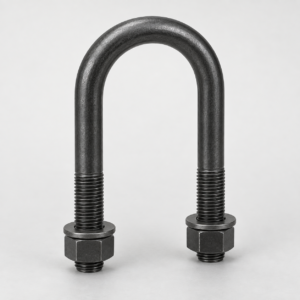
A pipe crossover plate kit with U-bolts is a bolted assembly that joins two round pipes or tubular structural members at 90 degrees without welding the members together. The typical kit uses one slotted steel crossover plate, four round-bend U-bolts, nuts, and washers: two U-bolts secure each member on opposite faces of the plate. YOUNGLEE supplies custom carbon-steel or stainless-steel kits for tower hardware, rooftop frames, equipment supports, handrails, utility structures, and other engineered tubular assemblies. Pipe outside diameters, plate geometry, U-bolt dimensions, material, coating, hardware, and documentation can be produced to an approved drawing. Final load capacity, member suitability, tightening, spacing, and environmental performance require project-specific engineering confirmation.
Pipe Crossover Plate Kit with U-Bolts at a Glance
| Product fact | Available project basis | Information for Buyer Confirmation |
|---|---|---|
| Product type | 90-degree pipe-to-pipe crossover clamp using one slotted plate and four U-bolts | Round-to-round, round-to-square, or another approved member combination |
| Primary function | Hold two tubular members perpendicular to each other through a removable bolted connection | Required angle, load directions, slip restraint, rotation restraint, and service duty |
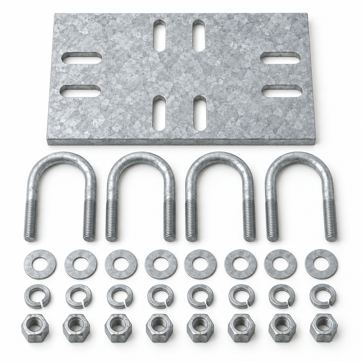
| Typical kit content | One crossover plate, four U-bolts, eight nuts, and drawing-specified flat or lock washers | Exact bill of materials, spare hardware, nut style, washer type, and packaging |
| Common materials | Carbon-steel plate and formed steel U-bolts; stainless-steel options where technically suitable | Material standards, grades, mechanical properties, heat treatment, and traceability |
| Finish options | Hot-dip galvanized, electro-zinc plated, plain, or project coating where compatible | Coating standard, thickness or class, thread allowance, repair method, and mating finish |
| Member size basis | Made around actual outside diameters and the approved plate slot pattern | Actual OD of both members, tolerances, coatings, ovality, and wall thickness |
| Customization | Plate length, width, thickness, slots, edge distances, U-bolt diameter, bend, leg length, and thread | Approved drawing revision, design actions, acceptance basis, tests, quantity, and documentation |
Customization Note: These are configurable supply options, not a universal stock series or load rating. The complete connection—including both supported members, plate, U-bolts, nuts, washers, coatings, tightening method, installation spacing, and all design actions—must be approved for the project.
What Is a 90-Degree Pipe Crossover Clamp?
A 90-degree pipe crossover clamp connects two round members whose axes cross at a right angle. One member bears against one face of the plate; the other bears against the opposite face. Two U-bolts capture each member, and their threaded legs pass through the plate slots or holes defined by the drawing. The plate separates the members, transfers contact forces, and provides a common bolted interface.
Buyers also use the terms U-bolt crossover plate, pipe-to-pipe crossover clamp, crossover plate kit, and pole-to-pole clamp. These names describe the same general connection concept, but they do not guarantee identical geometry. Plate thickness, slot arrangement, U-bolt count, pipe ranges, hardware grades, and coating systems vary between suppliers and projects.
How the connection carries load
Each pair of U-bolts develops clamping force around one tubular member and reacts through the plate. External forces can introduce U-bolt tension and bending, bearing against the pipe and plate, plate bending, slot-edge bearing, local pipe-wall deformation, frictional slip, prying, and nut-thread loading. Wind, equipment eccentricity, vibration, ice, thermal movement, maintenance loads, and accidental actions may act in different directions. A visually similar catalog kit is not evidence that a custom assembly has the same allowable load.
Why four U-bolts are commonly used
A common heavy-duty pipe-to-pipe arrangement uses two U-bolts for each member. The separated clamp points help resist rotation and distribute contact along the pipe. Some light-duty, universal, square-tube, or angle-member kits use different hardware. YOUNGLEE therefore treats the bill of materials as drawing-controlled rather than assuming that every crossover plate must contain four identical U-bolts.
How Does a Crossover Plate Kit Differ from Other U-Bolt Assemblies?
| Assembly | Members connected | Main selection inputs | Important distinction |
|---|---|---|---|
| Pipe crossover plate kit with U-bolts | Two tubular members at 90 degrees | Both actual ODs, angle, plate pattern, U-bolt geometry, actions, finish | Four-point crossover connection through a common plate |
| Standard pipe U-bolt | One pipe to a beam, channel, or support surface | Pipe OD, inside width, rod diameter, leg length, thread, grip or guide function | Controls one pipe rather than joining two crossing members |
| Strut beam clamp with U-bolt | Strut channel to structural beam flange | Channel profile, flange thickness, plate engagement, pair spacing, loads | Upper structural attachment; not a pipe-to-pipe crossover |
| Pipe-to-square-tube crossover kit | Round pipe to rectangular or square hollow section | Pipe OD, square-tube width and corner radius, backing plates, square U-bolts or bolts | Hardware and contact geometry differ from a round-to-round kit |
| Welded tubular connection | Members joined by a qualified weld detail | Base metals, weld procedure, fit-up, inspection, coating repair, loads | Permanent joint with a different design and inspection basis |
Customization Note: The comparison explains product identity and procurement inputs only. It does not establish interchangeability, structural equivalence, or permission to substitute one connection for another.
Dimensions Needed for a Custom U-Bolt Crossover Plate
Actual member dimensions are the starting point. Nominal pipe size, NPS, DN, antenna-mast descriptions, and trade names do not directly state outside diameter in every product system. The quotation drawing should identify each member separately and show which pipe sits on each plate face.
| Dimension or input | Why it matters | Information for Buyer Confirmation |
|---|---|---|
| Member A actual outside diameter | Controls the first U-bolt bend, inside width, and contact | Actual OD, tolerance, ovality, wall thickness, seam, coating, and member specification |
| Member B actual outside diameter | Controls the perpendicular U-bolt pair and the second slot group | Actual OD, tolerance, ovality, wall thickness, seam, coating, and member specification |
| Included angle | Defines the relationship between the two slot groups and load path | 90 degrees or another drawing-defined angle, including angular tolerance |
| Plate length and width | Provide space for both U-bolt pairs, edge distances, tools, and load distribution | Overall dimensions, corner treatment, orientation, clearance envelope, and tolerances |
| Plate thickness | Influences bending, slot bearing, stiffness, mass, and galvanizing behavior | Thickness, material grade, flatness, allowable deflection, and acceptance method |
| Slot size and center spacing | Control U-bolt fit, adjustability, edge distance, and positional tolerance | Slot width, length, end radius, direction, spacing, and whether adjustment is permitted |
| U-bolt rod diameter and bend | Affect strength, forming strain, contact area, nut selection, and hole fit | Rod diameter, inside width, bend radius, leg parallelism, and dimensional tolerances |
| Leg and thread length | Must accommodate pipe, plate, washers, nuts, coating, and installation access | Datum, usable thread, protrusion limits, full or partial thread, and thread runout |
| Thread and hardware | Determine nut compatibility, engagement, tightening tools, and coating allowance | Metric or Unified thread, pitch/TPI, class, nut standard, washer type, and locking method |
Customization Note: All dimensions must be coordinated on one approved assembly drawing. Nominal pipe descriptions are not substitutes for actual OD. If inch dimensions are supplied, the drawing should preserve the stated decimals and clearly define the conversion and tolerance basis.
Slot adjustment is not unlimited universality
Elongated slots can accommodate an intended size combination or installation tolerance, but they also affect bearing area, edge distance, and plate strength. A plate should not be marketed as universally suitable merely because a U-bolt can enter a slot. Confirm that every requested pipe combination leaves adequate material around the slots and permits washers and nuts to seat flat.
Material and Coating Selection
Carbon-steel plate and U-bolts
Carbon steel is common for outdoor and industrial crossover kits, particularly when a hot-dip galvanized finish is specified. The plate and U-bolts may require different product standards because one is a fabricated plate and the others are formed threaded hardware. The purchase order should identify the material grade and required mechanical properties for each component instead of using “steel” as the complete specification.
Hot-dip galvanized assemblies
ISO 1461:2022 specifies general properties and test methods for batch hot-dip galvanized coatings on fabricated iron and steel articles, while noting that fasteners with specific standards may require different provisions. ASTM A123/A123M covers hot-dip galvanized coatings on many fabricated iron and steel products and directs centrifuged hardware such as bolts toward ASTM A153/A153M. For a crossover kit, the buyer should state the applicable coating standard separately for the plate, U-bolts, nuts, and washers.
Galvanizing can affect slot clearance, thread fit, nut tapping, surface appearance, drainage, and assembly. Coating after forming is often selected for coverage of the finished U-bolt, but the required process, masking, thread allowance, repair, passivation, and inspection remain project decisions. Hot-dip galvanizing should not be described as automatically equivalent to electro-zinc plating.
Electro-zinc and project coating systems
Electro-zinc plating may be appropriate for controlled environments or where a thinner coating is required for thread fit. The coating thickness, passivation, sealant, hydrogen-embrittlement controls, and corrosion expectations must be stated. Painted, powder-coated, or duplex systems require compatible surface preparation and attention to nut seating and field damage.
Stainless-steel options
304/304L or 316/316L stainless steel can be considered where project corrosion conditions support the choice. Stainless steel does not create a universal marine or chloride-service rating. Grade, strength condition, forming behavior, galling prevention, nut pairing, surface finish, contamination control, and contact with galvanized or carbon-steel members all require review. Dissimilar-metal contact and water retention around the plate can govern durability.
Industry Reference Data and Its Limits
Manufacturer catalogs confirm that crossover plate kits have independent procurement intent and illustrate common selection fields. The following values remain attached to the named supplier products. They are not YOUNGLEE dimensions, ratings, certifications, or evidence of prior supply.
| Published industry example | Reference data | Safe interpretation | Information for Buyer Confirmation |
|---|---|---|---|
| ANDREW XP-2020-2025 crossover plate | For 2.375 in (60.325 mm) and 2.875 in (73.025 mm) OD combinations; 0.375 in (9.525 mm) plate; hot-dip galvanized steel; plates and U-bolts included | Confirms a configurable round-to-round product class and exact supplier-specific size example | Actual member ODs, plate size, slot layout, U-bolt dimensions, coating standard, hardware, loads, and acceptance basis |
| Site Pro 1 SCX45-K crossover kit | 2.875 in (73.025 mm) smaller member, 3.5 in (88.9 mm) larger member, 0.375 in (9.525 mm) plate, one plate plus four U-bolts and hardware | Confirms the common one-plate/four-U-bolt arrangement; published mass and dimensions remain supplier-specific | Required member pairing, exact bill of materials, plate geometry, fastener grade, coating, and structural verification |
| ISO 1461:2022 | General coating properties and test methods for batch hot-dip galvanized fabricated iron and steel articles | Potential coating basis for the fabricated plate when invoked by the purchase specification | Applicable standard, coating category/thickness basis, sampling, appearance, repair, documentation, and exclusions |
| ASTM A123/A123M and ASTM A153/A153M | A123/A123M addresses many fabricated iron and steel products; A153/A153M addresses hot-dip zinc coating on iron and steel hardware | Different kit components may require different coating standards | Standard and active edition for each component, thread fit, nut treatment, inspection, certification, and packaging |
Customization Note: Supplier catalog data are retained only as qualified industry references. YOUNGLEE dimensions and allowable loads, if required, must be established for the exact approved materials, geometry, coating, hardware, installation, and design actions.
Installation and Engineering Review
Confirm member position before tightening
Both pipes should contact the intended plate faces and align with the correct U-bolt pair. Washers and nuts must seat on flat surfaces without bridging slot ends or plate edges. Verify tool access, thread engagement, member coatings, and clearance from weld seams, fittings, holes, flanges, or existing attachments.
Use a defined tightening method
Tightening torque depends on thread size, material, coating, lubrication, nut type, washer system, and desired clamp behavior. A generic torque chart can produce excessive pipe-wall deformation, plate bending, coating damage, or insufficient slip resistance. The project drawing or installation procedure should define torque, turn-of-nut, snug-tight, prevailing-torque, or another approved method and any inspection marks or recheck interval.
Check the complete structure
The crossover kit is one connection within a larger frame. The two tubular members, their wall thickness and local bearing, adjacent mounts, welds, anchors, tower or rooftop structure, and connected equipment require independent verification. Do not use the assembly as a lifting point, life-safety anchor, fall-arrest attachment, or seismic restraint unless the exact system has been designed and approved for that duty.
Typical Applications
- Perpendicular tubular framing in communication, antenna, rooftop, and equipment-support structures;
- Secondary round-member attachments on poles, towers, racks, and utility frames;
- Bolted retrofits where welding the existing tubular members is not permitted;
- Handrail, barrier, agricultural, greenhouse, lighting-grid, and general fabricated-tube structures when engineered for the duty;
- Custom pipe-to-pipe fixtures, braces, or mounting frames made to an approved drawing.
For a single round pipe attached to a support surface, compare a zinc-plated carbon-steel U-bolt pipe clamp. For channel-to-beam framing, a strut beam clamp with U-bolt performs a different upper-attachment function. When the captured member is rectangular rather than round, review a custom square-bend U-bolt for rectangular tubing. These configurations are not interchangeable solely because each uses a U-bolt.
Representative Image Disclosure
The featured image is a newly generated representative flat-lay visual of an unassembled kit. It shows one slotted rectangular plate, four round-bend U-bolts, eight flat washers, eight split lock washers, and eight hex nuts on a neutral background. Pipes are intentionally omitted so the components and slot directions remain visible. The image does not establish dimensions, plate thickness, material grade, coating standard, hardware grade, load rating, certification, prior supply, or suitability for any project. The approved drawing and purchase specification control the delivered assembly.
What Should the Buyer Provide for Quotation?
- Actual outside diameter, wall thickness, tolerance, material, coating, and orientation of both members;
- Required included angle and whether adjustment, slip, or rotation must be prevented;
- Plate length, width, thickness, material, slot pattern, edge distances, corner treatment, and tolerances;
- U-bolt rod diameter, inside width, bend radius, leg length, thread length, thread specification, and tolerances;
- Nuts, flat washers, lock washers, locking feature, spare hardware, and complete bill of materials;
- Vertical, lateral, longitudinal, torsional, uplift, wind, ice, vibration, fatigue, seismic, and accidental design actions;
- Coating or passivation standard, thickness/class, repair method, thread fit, color, and mating-material requirements;
- Tightening procedure, installation access, inspection, calculation or test basis, marking, traceability, documentation, packaging, and quantity;
- Applicable drawing revision, standard, project specification, and acceptance criteria.
Frequently Asked Questions
Does nominal pipe size define the required crossover kit?
No. U-bolt fit and plate slot spacing are based on actual outside diameter, not nominal bore alone. Provide the actual OD and tolerance for both members, plus wall thickness, coating, and ovality where relevant.
Are the pipes included with the kit?
Not unless the quotation explicitly includes them. A typical crossover kit consists of the plate, U-bolts, nuts, and specified washers. The buyer should approve the bill of materials and any spare hardware.
Can one plate fit several pipe combinations?
Possibly, when the slot layout and structural checks are designed for those combinations. Slot adjustability does not prove universal fit or load capacity. Each OD pairing still requires adequate washer seating, edge distance, U-bolt geometry, and engineering approval.
Can YOUNGLEE supply the kit hot-dip galvanized?
Yes, where material, geometry, drainage, thread allowance, coating standards, and mating hardware are suitable. The purchase specification should identify the governing coating standard for the fabricated plate and separately for the U-bolts and hardware.
Is a catalog plate thickness also a YOUNGLEE standard thickness?
No. Values such as 0.375 in (9.525 mm) shown in named industry examples belong to those supplier configurations. YOUNGLEE plate thickness must be selected and approved for the requested member sizes, slot pattern, materials, actions, and acceptance basis.
Request a Quotation from YOUNGLEE
Send YOUNGLEE the two member drawings, actual outside diameters, required 90-degree arrangement, plate and U-bolt dimensions, design actions, material and coating specifications, complete hardware requirement, tightening method, inspection basis, quantity, and applicable standards. YOUNGLEE can review custom pipe crossover plate kits with U-bolts for production to an approved drawing or agreed specification. Final geometry, materials, finish, hardware, documentation, and acceptance requirements will be confirmed before manufacture.