A strut beam clamp with U-bolt is a paired, bolted attachment used to secure strut channel to a structural beam flange without drilling or welding the beam. Each clamp uses a formed U-bolt, a load-spreading clamp plate, and compatible nuts to capture the channel and engage the flange edge. YOUNGLEE supplies custom carbon-steel or stainless-steel assemblies to an approved drawing for mechanical, electrical, HVAC, utility, and industrial support frames. Channel profile, flange thickness, U-bolt diameter, plate geometry, material, finish, pair spacing, installation access, loads, and inspection requirements can be customized. Final capacity and suitability must be established for the complete pair, supporting beam, channel, fasteners, orientation, and service conditions.
Strut Beam Clamp with U-Bolt at a Glance
| Product fact | Available project basis | Information for Buyer Confirmation |
|---|---|---|
| Product type | Paired strut-to-beam attachment using formed U-bolts, clamp plates, nuts, and optional washers | Required support arrangement, channel location, beam orientation, and attachment function |
| Connection purpose | Secure a strut channel to a steel beam flange without field welding or drilling when the approved design permits | Vertical, lateral, uplift, longitudinal, vibration, seismic, and accidental actions |
| Common materials | Carbon steel; 304/304L or 316/316L stainless steel when technically suitable | Material specification, grade, mechanical properties, heat treatment, and traceability |
| Finish options | Plain, electro-zinc plated, hot-dip galvanized, or project coating where compatible | Coating standard, class or thickness, passivation, repair method, thread allowance, and mating finish |
| Channel interface | Clamp geometry made for the specified strut depth, width, lip, slot pattern, and installation orientation | Actual channel manufacturer/profile, dimensions, gauge, material, finish, and allowable channel load |
| Beam interface | Plate or jaw geometry proportioned to the actual flange edge and installation clearance | Beam section, actual flange width and thickness, taper or radius, edge condition, and coating |
| Supply format | One matched pair or drawing-defined set, with nuts and washers as specified | Pair quantity, hardware standards, tightening method, marking, inspection, and packaging |
| Customization | Production to approved drawing, sample, or agreed dimensional schedule | Drawing revision, quantity, acceptance criteria, documentation, and required tests |
Customization Note: These entries describe configurable supply options, not a universal stock range or load rating. The complete beam, channel, clamp pair, fasteners, installation orientation, clearances, finishes, and design actions require project-specific engineering approval.
What Is a Strut Beam Clamp with U-Bolt?
A strut beam clamp with U-bolt is an upper structural attachment for a channel support frame. It is also described in industry catalogs as a U-bolt beam clamp, channel-to-beam clamp, or strut channel beam clamp. The U-shaped rod passes around the strut member, while its threaded legs engage a steel clamp plate and nuts near the edge of the beam flange. A second matching clamp is normally placed at the other required attachment position so the channel is restrained as a pair.
This product is not the same as a round pipe U-bolt. A pipe U-bolt follows a pipe outside diameter and normally transfers force between the pipe and a support. A strut beam clamp instead fits a structural channel and a beam flange. The selection dimensions therefore come from the channel profile, flange geometry, load path, pair spacing, and installation access—not from pipe size.
How the load path works
The supported channel transfers its reactions into the curved U-bolt and clamp plate. The plate engages the beam flange edge, and the paired installation transfers the resulting forces into the structural beam. Contact pressure, local bending of the plate, U-bolt tension and bending, nut engagement, channel-wall bearing, flange-edge bearing, slip, and prying can all influence performance. The published capacity of one supplier-specific catalog item cannot be transferred to a custom assembly merely because the products look similar.
Why the clamps are installed in pairs
Industry product instructions state that this type of attachment requires installation in pairs and that the stated static load is based on one pair. A pair helps control rotation and distributes force between attachment points. Exact spacing and orientation are part of the engineered detail. Two loose clamps are not automatically a qualified pair: both must match the approved channel, beam flange, hardware, tightening procedure, and load direction.
How Does It Differ from Other U-Bolt and Beam-Clamp Products?
| Product arrangement | Member captured | Primary selection inputs | Important distinction |
|---|---|---|---|
| Strut beam clamp with U-bolt | Strut channel and structural beam flange | Channel profile, flange thickness, pair spacing, plate geometry, actions, finish | Upper attachment; normally used as a matched pair |
| Standard pipe U-bolt | Round pipe, tube, or conduit | Actual pipe OD, rod diameter, inside width, leg and thread length, grip/guide function | Fits the pipe rather than the beam flange |
| Window-style strut beam clamp | Strut channel and beam flange | Channel height, flange thickness, window geometry, design load | Uses a formed window body rather than a separate U-bolt and plate |
| Set-screw beam clamp | Beam flange and hanger rod or fitting | Flange thickness, throat depth, setscrew, rod size, load direction | Usually supports rod or fittings; it is not the same channel-capturing assembly |
| Welded channel attachment | Channel or bracket welded to structure | Base metal, weld detail, procedure, inspection, coating repair, loads | Permanent welded joint; different installation and inspection basis |
Customization Note: The comparison explains functions and procurement inputs only. It does not establish interchangeability, equivalent capacity, or approval for any particular structure. Select the attachment type through the responsible piping or structural engineer.
Dimensions Needed for a Custom Channel-to-Beam Clamp
A useful quotation drawing should define dimensions from functional datums. A catalog name such as “1-5/8-inch channel clamp” is insufficient because channel depth alone does not define width, lip return, wall thickness, corner radii, slots, material, or orientation. Beam section names also require confirmation against actual flange dimensions and tolerances.
| Dimension or input | Why it matters | Information for Buyer Confirmation |
|---|---|---|
| Channel width and depth | Controls the U-bolt clear opening and plate position | Actual measured profile, drawing, manufacturer/series reference, and tolerances |
| Channel wall thickness and lips | Affects bearing, clearance, and whether the U-bolt can seat correctly | Gauge or thickness, lip size, slot form, and open-side orientation |
| Beam flange thickness | Controls the required jaw or plate engagement and available thread length | Actual thickness at the clamp location, including taper, mill tolerance, paint, or galvanizing |
| Beam flange edge geometry | Determines plate contact and avoidance of root radius or obstructions | Flange width, edge condition, fillet/root radius, taper, and usable access |
| U-bolt rod diameter and thread | Influences strength, nut selection, hole size, engagement, and installation tools | Metric or Unified thread, diameter, pitch/TPI, class, thread length, and required nut standard |
| Inside width and inside height | Must clear the channel while limiting unintended movement | Dimensional datum scheme, bend radius, channel coating allowance, and installation gap |
| Clamp-plate width, length, and thickness | Controls contact, bending, prying, and edge engagement | Plate material, hole spacing, edge distances, profile, and permissible local contact |
| Pair spacing and orientation | Controls load distribution and resistance to rotation | Center-to-center spacing, side of flange, channel direction, and installation sequence |
Customization Note: Dimensions must be approved as a coordinated assembly. If inch dimensions are supplied, YOUNGLEE preserves every decimal place provided and multiplies the unrounded value by 25.4 for millimetre conversion; any reporting precision or tolerance remains subject to the buyer’s drawing.
Actual dimensions take priority over nominal descriptions
Nominal channel names and beam section designations are useful references, but fabrication requires the actual controlled dimensions. Coatings can reduce clearances, tapered flanges change contact, and channel lips may interfere with the U-bolt bend. A sample or section drawing is valuable when the channel series is not fully identified.
Material and Finish Selection
Carbon steel for general industrial frames
Carbon steel is a common starting point where the environment, required strength, forming process, weldability of any separate plate, and maintenance plan permit. “Carbon steel” alone is not a finished specification. The purchase order should identify the U-bolt material, plate material, required mechanical properties, heat treatment if any, and documentation. A plate and U-bolt need not use the same product standard, but their compatibility must be reviewed.
Electro-zinc plating for controlled exposure
ASTM B633 covers electrodeposited zinc coatings on iron and steel articles and classifies coating thickness and supplementary finishes. It also addresses process controls related to hydrogen embrittlement. Electro-zinc plating is relatively thin and can help preserve thread fit, but coating class, passivation, sealant, appearance, and service environment must be specified. It should not be described as equivalent to hot-dip galvanizing.
Hot-dip galvanizing for fabricated steel and hardware
Different galvanizing standards can apply to different components. ASTM A123/A123M covers hot-dip zinc coatings on many fabricated iron and steel products, while ASTM A153/A153M applies to iron and steel hardware handled to remove excess zinc. The buyer should define which standard governs the channel, plate, U-bolt, nuts, and washers. Thread allowances, oversize tapped nuts where applicable, coating drainage, surface repair, and fit after coating require confirmation before production.
Stainless steel for corrosion-resistant assemblies
304/304L or 316/316L stainless steel may be considered where base-metal corrosion resistance is preferred, but grade selection depends on chlorides, temperature, crevice conditions, cleaning chemicals, and contact with the carbon-steel beam or channel. Dissimilar-metal contact and coating damage can create corrosion risks. Stainless material does not remove the need to verify strength, galling control, nut pairing, surface condition, and structural compatibility.
Industry Reference Data and Its Limits
Manufacturer catalogs are useful for confirming that the product class has independent procurement intent and for identifying selection fields. They are not YOUNGLEE test reports. The examples below remain attached to the named suppliers’ configurations and cannot be used as a design value for a custom assembly.
| Published industry example | Reference condition | Safe interpretation | Information for Buyer Confirmation |
|---|---|---|---|
| nVent CADDY strut beam clamp with U-bolt | Complete with U-bolt and nuts; installation in pairs; published static load based on one pair | Confirms paired installation and cataloged product identity; it does not rate a YOUNGLEE assembly | Required load basis, safety factor, direction, pair spacing, channel/beam geometry, and test or calculation method |
| Eaton B-Line B441-22 family | Catalog examples list defined channel-height ranges, maximum flange thickness, finish options, and 1200 lbf (5.34 kN) design load | The 1200 lbf value belongs to the listed Eaton configuration and stated catalog conditions only | Project-specific allowable reactions and whether a supplier catalog series, custom calculation, prototype test, or other acceptance basis is required |
| ANSI/MSS SP-58-2025 | Industry framework for materials, design, manufacture, selection, application, inspection, and installation of pipe hangers and supports | May be specified as a governing framework; mentioning it is not a compliance claim | Applicable edition, support classification, project additions, load combinations, documentation, and inspection |
Customization Note: All loads and dimensional limits in third-party catalogs remain supplier-specific industry references. YOUNGLEE load ratings, if required, must come from an approved calculation or agreed test program for the exact materials, geometry, finish, hardware, installation, and load directions.
Installation and Engineering Review
Confirm the pair before tightening
Verify that both clamps are the same approved configuration and that the channel sits at the specified position and orientation. The clamp plates should make the intended contact without riding on a flange radius, weld bead, obstruction, or damaged coating. Nuts should engage the specified number of threads, and sufficient tool clearance must remain for controlled tightening and inspection.
Do not use tightening torque as an invented capacity
Installation torque depends on thread size, pitch, material, coating, lubrication, nut type, prevailing-torque feature, and the required joint behavior. A generic torque copied from a bolt chart may over-stress the plate, crush the channel, damage the coating, or create an unintended slip-critical assumption. The drawing or installation procedure should define the tightening method and any inspection marks or recheck requirements.
Check the complete supporting system
The clamp pair is only one link in the support load path. The beam, channel, brackets, hanger rods, anchors, pipe attachments, and connected equipment all require independent verification. Local beam-flange bending, channel flexure, eccentricity, vibration, thermal movement, uplift, seismic loads, fire-protection listing, and fatigue duty may govern even when the clamp hardware appears adequate.
Typical Applications
- Attaching strut channel below structural steel for mechanical and utility support frames;
- Supporting hanger rods, brackets, or secondary framing from a channel cross-member;
- Industrial retrofits where the approved design avoids field drilling or welding of the beam;
- HVAC, plumbing, electrical, instrumentation, and service-support structures;
- Temporary or adjustable bolted framing when the responsible engineer permits the arrangement.
For piping projects, this upper attachment may connect to a lower support such as an adjustable clevis pipe hanger. Where the pipe bears from below instead, compare a pipe saddle support with U-bolt or a welded pipe shoe with wear plate. These products perform different functions and are not interchangeable solely because they belong to one support assembly.
Representative Image Disclosure
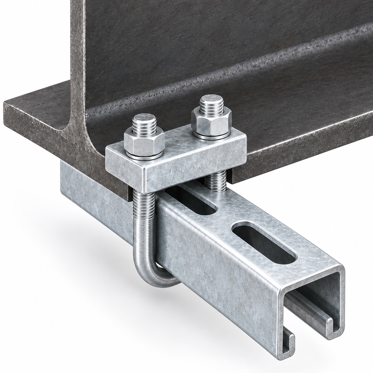
The featured image is a newly generated representative catalog visual of one clamp unit, one short slotted strut channel, and one beam-flange segment. It illustrates the U-bolt, plate, nuts, and contact concept. The image does not prove dimensions, material grade, coating specification, installed pair spacing, allowable load, certification, listing, prior supply, or suitability for a project. Actual installations normally use a matched pair as defined by the approved design; the second clamp is intentionally omitted from the close-up so the geometry of one unit remains visible.
What Should the Buyer Provide for Quotation?
- Beam section and actual flange width, thickness, edge profile, radius, material, finish, and orientation;
- Strut channel profile drawing, width, depth, wall thickness, lips, slots, material, finish, and orientation;
- Required pair arrangement, spacing, quantity per support, and installation access;
- Vertical, lateral, longitudinal, uplift, vibration, seismic, fatigue, and accidental design actions;
- U-bolt material, rod diameter, thread specification, inside dimensions, thread length, and hardware standards;
- Clamp-plate material, geometry, thickness, hole spacing, edge distances, and contact requirements;
- Coating or passivation standard, thickness/class, color, repair, thread-fit, and mating-material requirements;
- Tightening method, inspection, testing, marking, traceability, documentation, packaging, and quantity;
- Applicable drawing, standard, project specification, and acceptance criteria.
Frequently Asked Questions
Can one strut beam clamp be used by itself?
Do not assume so. Industry references for this U-bolt arrangement state that clamps are installed in pairs and rate the pair rather than one isolated unit. The project drawing must define the number, spacing, and orientation.
Does the clamp eliminate all welding and drilling?
It can provide a bolted attachment without field welding or drilling the beam when the responsible engineer approves that detail. Other parts of the support frame may still require welding, drilling, anchors, or separate structural connections.
Is a 1200 lbf catalog rating available for every custom clamp?
No. The 1200 lbf (5.34 kN) figure is an industry-catalog example tied to named configurations and conditions. A custom YOUNGLEE assembly requires its own approved design basis, calculation, or test program.
Can the assembly be supplied hot-dip galvanized?
Yes, where the selected materials, geometry, threads, drainage, coating standards, and mating components are suitable. The buyer must distinguish requirements for fabricated steel parts from requirements for fastener hardware and confirm thread allowance after galvanizing.
Which is more important: nominal channel size or actual profile?
The actual profile is controlling. Width, depth, wall thickness, lips, slots, corner radii, coating, and orientation affect fit and load transfer. Provide a dimensioned channel drawing or sample rather than a trade name alone.
Request a Quotation from YOUNGLEE
Send YOUNGLEE the beam and strut drawings, required paired arrangement, design actions, material and finish specifications, U-bolt and plate dimensions, tightening method, inspection requirements, quantity, and applicable standard. YOUNGLEE can review custom strut beam clamps with U-bolts for production to an approved drawing or agreed specification. Final geometry, hardware, coating, documentation, and acceptance requirements will be confirmed before manufacture.