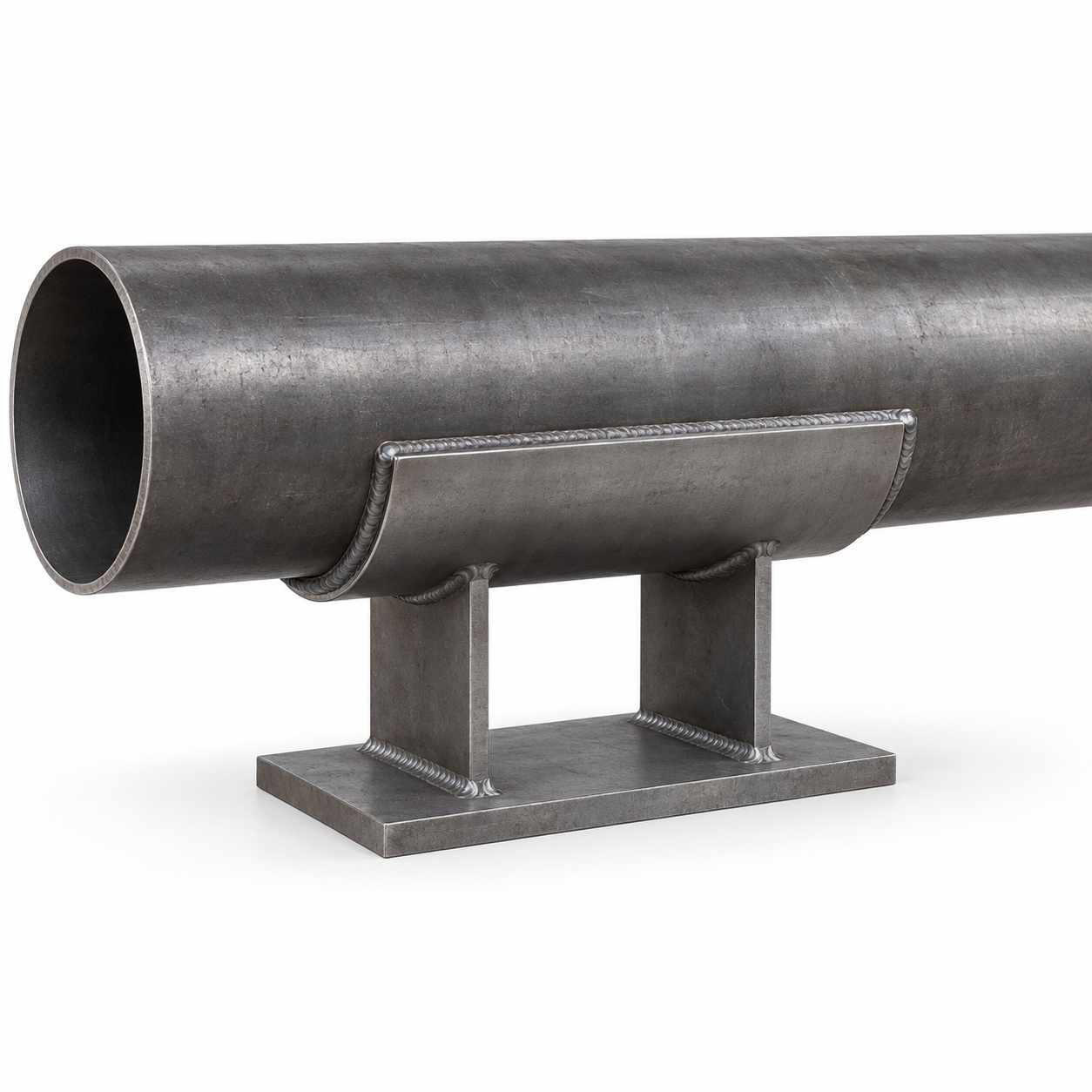
A welded pipe shoe is a fabricated steel support attached directly to a pipe or to a curved wear plate on the pipe. The wear plate spreads the interface, while one or more vertical webs transfer the pipe reaction to a flat base that bears on structural steel, a slide plate, or another engineered support surface. This arrangement can support bare or insulated process piping without concentrating the entire reaction at a narrow line of contact. YOUNGLEE manufactures custom welded pipe shoes in carbon steel or project-specified stainless steel to an approved drawing. Pipe outside diameter, support height, loads, movement function, material compatibility, weld details, finish, inspection, and documentation must be confirmed for each project; the page does not assign a universal load or temperature rating.
Image note: the product visual is a generated representative of a generic welded shoe with a curved wear plate, twin webs, and base plate. It does not prove project dimensions, material grade, weld procedure, capacity, movement function, coating, testing, certification, or previous supply.
Welded Pipe Shoe at a Glance
| Selection item | Typical custom supply basis | Information for Buyer Confirmation |
|---|---|---|
| Product type | Curved wear plate, one or two structural webs, and a flat base plate fabricated as a pipe shoe | Approved support drawing, configuration, dimensions, and revision |
| Primary function | Transfer vertical pipe reaction to supporting steel while maintaining a specified support elevation | Support, sliding, guiding, hold-down, or anchoring duty and all reaction directions |
| Pipe interface | Welded directly to compatible pipe material or welded through a drawing-defined curved wear plate | Parent-pipe specification, wall thickness, corrosion allowance, weldability, pressure-boundary review, and owner approval |
| Materials | Carbon steel or project-specified stainless steel, subject to fabrication and welding review | Material standard, grade, product form, condition, impact requirements, temperature, and traceability |
| Geometry | Custom pipe radius, wear-plate length, shoe length, web spacing, support height, base width, and plate thicknesses | Actual pipe OD, insulation clearance, loads, movement, supporting-steel width, and interference envelope |
| Surface condition | Plain, painted, hot-dip-galvanized where suitable, or another approved project finish | Coating standard, service exposure, temperature, weld sequence, field repair, contact surfaces, and drainage |
| Inspection | Drawing-defined dimensional, material, visual-weld, coating, and documentation checks | NDE method and extent, acceptance criteria, certificates, hold points, marking, and third-party inspection |
Customization Note: This table is a procurement framework, not a stock size series or certified capacity schedule. Final plate sections, welds, support height, loads, temperature basis, material, finish, movement function, and inspection requirements must be approved for the actual piping system before production.
How Does a Welded Pipe Shoe Carry the Pipe Load?
The vertical reaction begins in the pipe wall, passes through the attachment weld or wear plate, enters the shoe webs, crosses the base plate, and ends at the supporting structure or bearing interface. Every part of that path matters. Pipe-wall strength, local stress, weld geometry, wear-plate fit, web buckling, base-plate bending, bearing area, structural-steel capacity, and any slide surface can each govern the completed support.
A shoe that looks robust in a photograph therefore has no reliable capacity until the drawing and calculation basis are known. YOUNGLEE manufactures the approved geometry and can provide material and fabrication records when ordered, but the responsible piping and structural engineers must define design reactions, combinations, allowable stresses, local pipe checks, displacement, and installation conditions.
What does the curved wear plate do?
A curved wear plate, also called a reinforcement pad or repad in some project documents, increases the attachment footprint and provides a controlled interface between the pipe and shoe. It can help distribute load and keep the shoe webs from attaching at only a narrow location. It does not automatically strengthen every pipe or make a weld acceptable. Pad thickness, length, arc, material compatibility, edge preparation, weld details, vent or inspection provisions, and corrosion behavior must follow the approved design.
Why use two webs?
A double-web arrangement gives two parallel load paths between the curved top element and base plate and can improve lateral stability when properly proportioned. Web spacing also affects access for welding, coating, inspection, drainage, and attachment to the base. Single-web, T-bar, double-web, saddle, and split-shoe arrangements are different configurations; the drawing must identify the intended one instead of relying on the generic term pipe shoe.
Support, Slide, Guide, or Anchor: Define the Function
| Function | Intended behavior | Drawing inputs that change | Important caution |
|---|---|---|---|
| Resting support | Carries vertical reaction while the base bears on supporting steel | Bearing length, base width, support height, structure interface, and uplift condition | Do not assume friction provides a defined horizontal restraint |
| Sliding support | Allows specified axial and/or lateral thermal movement across a designed bearing interface | Travel, slide-plate materials, contact pressure, temperature, edge distance, and installation offset | Friction and movement range are project-specific; a plain base is not automatically low-friction |
| Guided shoe | Allows selected movement while limiting transverse displacement or rotation | Guide gap, guide height, wear surfaces, lateral reactions, travel, and erection tolerance | Guide members and gaps must not bind throughout the full movement envelope |
| Anchor shoe | Transfers defined vertical, axial, lateral, uplift, and moment reactions into the structure | Anchor lugs, base connection, welds or bolts, load combinations, and structural verification | An anchor is not created merely by welding a standard sliding shoe to steel |
| Hold-down or restraint | Controls uplift or a limited direction of movement without necessarily acting as a full anchor | Clips, lugs, gaps, clearances, impact allowance, and restraint reactions | Restraint direction and allowable movement must be stated explicitly |
Customization Note: The functions above are not interchangeable catalog labels. The project stress analysis and support drawing must identify permitted movement, restraint directions, reactions, friction assumptions, guide gaps, offsets, and structural connection before the shoe is manufactured.
Material and Finish Selection
Carbon structural steel is a common choice for fabricated wear plates, webs, and bases when project temperature, weldability, toughness, and corrosion rules permit it. Stainless steel may be selected for a corrosive environment or to match a defined piping material system. The purchase order should state the complete material specification and grade for every part rather than calling only for carbon steel or stainless steel. Plate grade, parent-pipe grade, filler metal, heat treatment, impact requirements, and dissimilar-metal contact all need coordinated review.
ASTM A36/A36M is one example of a structural carbon-steel plate specification used for general welded construction, while ASTM A240/A240M covers stainless plate, sheet, and strip for pressure-vessel and general applications. Naming either standard does not prove that it is suitable for a particular pipe attachment. The selected material must remain compatible with the parent pipe, welding procedure, design temperature, corrosion environment, applicable piping code, and owner specification.
| Option | Potential reason to specify | Items requiring confirmation |
|---|---|---|
| Plain carbon steel | Fabrication or field welding followed by a project-defined coating process | Temporary corrosion protection, final coating, weld cleaning, storage, and site repair |
| Painted carbon steel | Controlled atmospheric exposure under an approved paint system | Surface preparation, primer/topcoat system, dry-film thickness, temperature, contact areas, and repair |
| Batch hot-dip-galvanized fabrication | Durable zinc coating on suitable fabricated carbon-steel parts | ISO 1461 or project standard, venting and drainage, distortion risk, weld chemistry, coating thickness, and field repair |
| Stainless steel | Project material compatibility or corrosion resistance in a defined environment | Exact grade, product form, surface condition, chloride exposure, temperature, filler metal, pickling/passivation, and galvanic isolation |
| Slide-bearing interface | Reduced friction for planned thermal movement | Upper and lower materials, pressure, temperature, friction basis, travel, bonding or bolting, and replacement access |
Customization Note: Material and finish options are conditional supply choices, not automatic recommendations. Galvanizing, paint, stainless steel, and slide materials have different fabrication, temperature, welding, corrosion, and inspection constraints that must be resolved on the approved project specification.
What Data Controls Pipe Shoe Dimensions?
Nominal pipe size alone is insufficient. The curved wear plate must be fitted to the actual pipe outside diameter, while shoe height is normally driven by insulation clearance, support elevation, drainage, nearby steel, and the required movement path. Shoe length and base width depend on reactions, allowable bearing, supporting-steel geometry, slide travel, fabrication stability, and local pipe checks.
The quotation drawing should define the actual pipe OD, wear-plate arc and length, overall shoe length, support height, web thickness and spacing, base-plate width and thickness, weld symbols, end details, chamfers, drain or vent provisions, and tolerances. When inch dimensions are supplied, YOUNGLEE preserves every decimal place provided and multiplies the unrounded inch value by 25.4 for conversion to millimetres. Rounding the inch input before conversion can shift fit, elevation, guide gap, or hole location.
| RFQ input | Why it matters | Typical output affected |
|---|---|---|
| Pipe size, schedule, and actual OD | Controls fit and supports the local pipe-wall assessment | Wear-plate radius, arc, tolerance, weld access, and inspection gauge |
| Parent-pipe material and wall thickness | Controls weldability, local stress, heat treatment, and material compatibility | Wear-plate material, welding requirements, attachment detail, and documentation |
| Operating, test, occasional, and erection reactions | Different load combinations can govern different components | Wear plate, webs, base, welds, bearing area, and structural connection |
| Temperature and insulation | Affect material strength, support height, heat flow, coating, and clearance | Elevation, plate grades, finish, insulation cutout, and thermal design review |
| Axial and lateral movement | Defines travel, offsets, guide gaps, and bearing-surface length | Base dimensions, slide plates, guides, installation position, and end clearance |
| Support steel and connection | The shoe must land on and transfer load into a real structural member | Base width, bearing length, weld/bolt arrangement, anchor detail, and access |
| Corrosion environment | Wet insulation, chemicals, marine exposure, and dissimilar metals change material and coating risk | Material, coating system, isolation, drainage, seal details, and inspection plan |
| Inspection and documentation | Acceptance cannot be added reliably after fabrication | Material certificates, WPS/PQR and welder records, NDE, dimensional report, coating records, and marking |
Customization Note: These inputs support quotation and design review; they do not constitute a calculation or guaranteed rating. The responsible engineers must approve capacity, local pipe stresses, fatigue or cyclic effects, weld design, friction, travel, guide loads, anchor loads, insulation details, and structural adequacy.
Welding and Pressure-Boundary Interface
Attaching a shoe directly to process pipe can affect the pressure boundary and must follow the applicable piping code, owner specification, approved weld detail, and qualified welding procedure. The review should address parent-pipe chemistry and thickness, preheat, heat input, filler metal, weld size and length, access, distortion, residual stress, required postweld heat treatment, hardness or impact limits, and examination. The support fabricator should not choose these variables from a catalog image.
A wear plate can separate the structural webs from the pipe surface and enlarge the attachment area, but its edge welds still interact with the parent pipe. Sealed details can also trap moisture or make inspection difficult if drainage and venting are not designed. For critical, cyclic, high-temperature, low-temperature, thin-wall, lined, clad, or corrosion-sensitive service, the project engineering authority should approve the complete detail before material cutting begins.
Installation and Inspection Checks
- Verify the pipe identification, actual OD, wall thickness, shoe tag, drawing revision, material, and intended support location.
- Confirm that the pipe surface, wear plate, web spacing, base orientation, and weld preparations match the approved drawing.
- Set the shoe elevation, longitudinal position, and rotation without forcing the pipe or introducing unintended cold spring.
- Apply the approved welding sequence and protect nearby coatings, linings, insulation, and slide-bearing materials from heat and contamination.
- Confirm base bearing, guide gaps, travel allowance, installation offset, edge distance, and structural connection after welding.
- Complete the specified visual examination, NDE, dimensional inspection, coating repair, marking, and record package before release.
A shoe resting on a beam should not be field-welded to that beam unless the drawing identifies it as an anchor or another fixed connection. Likewise, a guide must retain its intended clearance over the full movement range. Installation changes can alter the stress-model assumptions and should be referred to the responsible engineer.
Where Are Welded Pipe Shoes Used?
Typical applications include refinery and chemical-process pipe racks, power and utility piping, industrial steam and condensate lines, water and wastewater plants, marine or offshore modules, and other systems where a defined elevation and robust fabricated load path are required. A higher shoe can carry the pipe above insulation or nearby steel, while a base with an engineered slide interface can accommodate thermal movement.
The same product family should not be used indiscriminately. Low-temperature insulated piping may require a purpose-designed cold shoe and vapor barrier; high-temperature insulation can require load-bearing insulation and thermal analysis; nonmetallic pipe needs its own support and contact-pressure rules. These are separate engineered assemblies, not ordinary welded steel shoes with a different marketing label.
How Does This Product Differ from Other YOUNGLEE Supports?
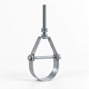
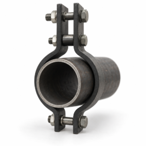
A pipe saddle support with U-bolt uses a formed cradle and mechanical retainer on a stanchion, so it can suit projects that prefer a removable clamp rather than a shoe welded to the pipe. An adjustable steel pipe roller stand supports a line on a rotating contact surface and provides elevation adjustment for a different movement strategy. A three-bolt pipe clamp suspends insulated horizontal piping from above and keeps its load connection outside the insulation envelope. The correct choice depends on support direction, movement, insulation, pipe attachment restrictions, maintenance access, and the project stress model.
Frequently Asked Questions
Is a wear plate always required below a welded pipe shoe?
No. Some approved details weld the shoe directly to the pipe; others use a curved wear plate to enlarge the attachment zone or address a project-specific interface. The piping engineer must select the detail after reviewing parent-pipe material, wall thickness, local stress, welding, corrosion, inspection, and service conditions.
Can the base plate slide directly on structural steel?
It can be designed as a plain bearing support, but the resulting friction and wear must be included in the piping analysis. Where lower or controlled friction is required, the drawing should specify a compatible slide-bearing pair, design pressure, temperature, movement, attachment method, and replacement access.
Does MSS SP-58 provide one universal pipe-shoe size table?
No universal YOUNGLEE size or capacity should be inferred from the standard name. ANSI/MSS SP-58 provides an industry basis for pipe hanger and support materials, design, manufacture, selection, application, inspection, and installation. The project must still identify its standard edition, support drawing, dimensions, materials, load basis, and acceptance criteria.
Can a welded pipe shoe be hot-dip galvanized?
Suitable fabricated carbon-steel parts may be specified for batch hot-dip galvanizing under ISO 1461 or another approved project standard. The designer and galvanizer must review fabrication sequence, venting and drainage, distortion, weld chemistry, contact surfaces, coating thickness, field welds, and repair. The parent pipe is not automatically included in that coating scope.
What should an RFQ include?
Provide the pipe specification, NPS or DN, schedule and actual OD; operating and design temperatures; insulation; all support reactions; axial and lateral movement; shoe length and height; wear-plate, web, and base dimensions; material grades; weld details; support/slide/guide/anchor function; surface treatment; supporting-steel information; quantity; inspection; certificates; marking; packaging; and the latest drawing.
Request a Quote for a Custom Welded Pipe Shoe
Send YOUNGLEE the approved drawing or the complete pipe and support data listed above. Our technical team will review manufacturing feasibility, material compatibility, curved wear-plate fit, web and base fabrication, weld access, finish, inspection, documentation, and dimensional controls before quotation. Products can be manufactured to the agreed drawing or applicable standard with custom dimensions and project-specific quality requirements. Final structural capacity, pipe local stress, welding approval, movement function, temperature suitability, and installation design remain subject to project engineering confirmation.