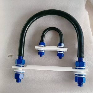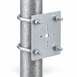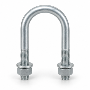
An insulated U-bolt clamp for HDPE pipe is a drawing-controlled support assembly that holds or guides polyethylene pipe without placing bare metal directly against the pipe wall. YOUNGLEE supplies custom round U-bolts, compatible nuts and washers, a broad support plate or cradle, and project-selected elastomer or composite isolation materials. This configuration is used for above-ground HDPE water, slurry, industrial, marine, and utility piping where actual outside diameter, DR or SDR, loaded weight, temperature movement, support function, and surface protection must be reviewed together. Grip, guide, and hold-down duties are not interchangeable; dimensions, clearances, pad materials, finishes, and hardware are customized to an approved drawing or applicable project standard.
Insulated U-Bolt Clamp for HDPE Pipe at a Glance
| Selection item | YOUNGLEE supply basis | Information for Buyer Confirmation |
|---|---|---|
| Product type | Round U-bolt assembly with an insulated contact surface and a broad lower support interface for HDPE pipe | Clamp, hold-down, guide, or other drawing-defined function |
| Pipe definition | Custom fit to the stated actual outside diameter; nominal DN, NPS, or trade size is not used alone | Pipe standard, OD series, DR or SDR, minimum wall, ovality allowance, and any outer jacket |
| Metal options | Carbon steel or stainless steel, subject to technical and commercial review | Required grade, fastener compatibility, corrosion environment, and material documentation |
| Isolation options | Neoprene or another approved elastomer sleeve; cork-neoprene, elastomeric, thermoplastic, or engineered composite bearing pad where specified | Material grade, thickness, hardness, temperature, chemical exposure, fire or smoke requirements, and test basis |
| Finish options | Plain, zinc electroplated, hot-dip galvanized, coated, or stainless construction as the drawing permits | Coating standard, thickness or class, repair method, thread fit, and compatibility with pads and pipe |
| Typical applications | Above-ground HDPE pipe supports, utility racks, mine and slurry lines, marine services, treatment plants, and industrial pipework | Service fluid, filled weight, pressure condition, temperature range, environmental exposure, vibration, and accidental loads |
| Reference standards | Pipe OD may be defined by ASTM F714, ASTM D3035, ISO 4427-2, AWWA C906, or another project pipe specification | Exact standard and edition; the pipe standard does not define the complete clamp |
| Customization | Inside width, bend radius, rod diameter, leg and thread lengths, plate geometry, pad system, hardware, finish, and inspection plan | Approved support drawing, loads, movement, installation stack, quantity, and acceptance criteria |
Customization Note: These are available design inputs, not a universal stock series or guaranteed operating envelope. Final dimensions, materials, pad properties, loads, movement, tightening, and documentation must be confirmed against the actual HDPE pipe, service conditions, support spacing, structural interface, and approved drawing before manufacture.
Why Does HDPE Pipe Need a Purpose-Designed U-Bolt Support?
HDPE is flexible and responds differently from steel pipe at a support. A narrow metal edge, excessive nut preload, an incorrect bend radius, or an undersized contact surface can concentrate pressure and may promote local flattening, indentation, abrasion, or restricted thermal movement. The clamp therefore has to be selected as part of the pipe-support system rather than as an isolated piece of threaded rod.
For above-ground polyethylene piping, the Plastics Pipe Institute identifies temperature, pressure, fluid weight, support spacing, deflection, and expansion or contraction as connected design considerations. Its guidance also distinguishes supports that grip the pipe from supports that guide free movement. YOUNGLEE uses the buyer’s pipe data and approved support detail to manufacture the metal and isolation components; the piping designer remains responsible for the system analysis and allowable reactions.
Broad support and protected contact
The lower plate or cradle should spread bearing over a defined area and keep sharp edges away from the pipe. A resilient or composite pad can separate the HDPE from galvanized, coated, or stainless hardware and may reduce abrasion or contact concentration. Pad width, length, thickness, compressibility, creep, chemical compatibility, and temperature resistance are project variables. A material name by itself does not establish suitability.
Controlled nut position instead of uncontrolled tightening
A U-bolt can look correctly installed while still applying the wrong preload. The drawing should state the installed gap or clamp position, washer arrangement, double-nut or locking method, and any torque or dimensional acceptance rule. For a guide, the nuts normally establish clearance rather than force the pipe tightly into the support. For a grip or hold-down, the designer must verify that the pipe wall and complete support can accept the resulting contact and restraint forces.
Clamp, Hold-Down, or Guide: Choose the Function First
| Function | What the assembly is intended to do | Critical details to define |
|---|---|---|
| Grip clamp | Restrains the pipe by controlled contact around or against the pipe | Allowable pipe deformation, contact pressure, pad area, preload method, restraint loads, and inspection |
| Hold-down clamp | Limits uplift while vertical bearing is carried mainly by the lower support | Installed top clearance, uplift reaction, lateral gap, hardware locking, and support-plate stiffness |
| Guide / non-grip clamp | Controls selected lateral movement while allowing movement in the intended axial direction | Guide gap, travel, friction interface, wear allowance, end stops, thermal movement, and installation tolerance |
| Anchor or fixed point | Transfers defined longitudinal, lateral, and uplift reactions into the supporting structure | Engineered pipe restraint, complete load path, pipe stress check, welds or bolts, structure, and qualified calculations |
Customization Note: The same-looking U-bolt must not be assumed to perform all four functions. YOUNGLEE manufactures the approved arrangement, but the piping and structural designers must define the required degrees of freedom, reactions, gaps, pad behavior, and acceptance criteria.
A guide arrangement is especially relevant where HDPE temperature change produces appreciable axial movement. If the project instead calls for a true fixed point, a simple U-bolt around flexible pipe may be insufficient. The designer may need a purpose-engineered restraint, a wider clamping system, fused or mechanical features, or a different support concept. The product page does not assign an anchor capacity or approve a system design by appearance.
How to Size an HDPE Pipe U-Bolt Clamp
Start with the pipe’s actual outside diameter, not only DN, NPS, IPS, DIPS, or a nominal trade size. ASTM F714 covers several outside-diameter sizing systems for larger PE pipe, while ASTM D3035 addresses smaller controlled-OD pipe ranges. ISO 4427-2 defines metric polyethylene pipe for specified applications. These references govern the pipe; they do not automatically define the U-bolt inside width, pad compression, support span, or installed clearance.
DR and SDR relate outside diameter to wall thickness. Two pipes with a similar nominal size can have different wall construction, stiffness, pressure basis, jacket, or dimensional tolerance. The clamp quotation should therefore include the exact pipe manufacturer data or project table whenever available. YOUNGLEE will preserve every decimal place supplied in an inch dimension. Inch values are converted to millimetres using the unrounded value multiplied by 25.4, because rounding before conversion can create a meaningful fit error.
Dimensions that belong on the support drawing
- Actual pipe outside diameter, OD tolerance, ovality, and any protective or insulation jacket.
- U-bolt rod diameter, inside width, inside height, bend radius, leg length, thread length, and thread specification.
- Lower plate or cradle width, length, thickness, hole spacing, edge radii, and structural attachment.
- Isolation sleeve coverage, wall thickness, termination at the start of the thread, and any seam or bonding requirement.
- Composite or elastomer pad material, thickness, contact area, hardness or compressibility, and retention method.
- Washer, nut, double-nut, locking, coating allowance, installed gap, and required thread projection.
Frequently Asked Questions
Is an HDPE U-bolt sized by DN or NPS?
No. DN or NPS is useful identification, but the clamp must be based on the actual pipe outside diameter, dimensional standard, tolerance, DR or SDR, ovality, and any jacket. Send the pipe data sheet or approved OD table with the inquiry.
Can this clamp allow thermal movement?
Yes, if it is engineered as a guide or non-grip arrangement with the required clearance, bearing surface, friction basis, wear allowance, and travel. A grip clamp or fixed point has a different duty and must be designed for the resulting reactions.
Does the neoprene sleeve set the load rating?
No. Assembly capacity depends on the pipe, contact area, plate, U-bolt, hardware, pad behavior, support spacing, temperature, structural connection, and load cases. The sleeve protects or isolates contact; it does not establish a standalone safe working load.
Can YOUNGLEE use stainless steel?
Stainless options can be reviewed against the required grade, environment, thread system, galling controls, hardware, and isolation plan. The buyer should not substitute stainless for coated carbon steel without reviewing the complete assembly and project specification.
What should be included with an RFQ?
Provide the actual HDPE pipe OD, pipe standard and edition, material designation, DR or SDR, wall thickness, loaded condition, operating and installation temperatures, support function, reactions and travel, U-bolt dimensions, plate or cradle drawing, pad and sleeve specification, metal grade, finish, hardware, inspection documents, quantity, and applicable project standard.
Representative Image Notice
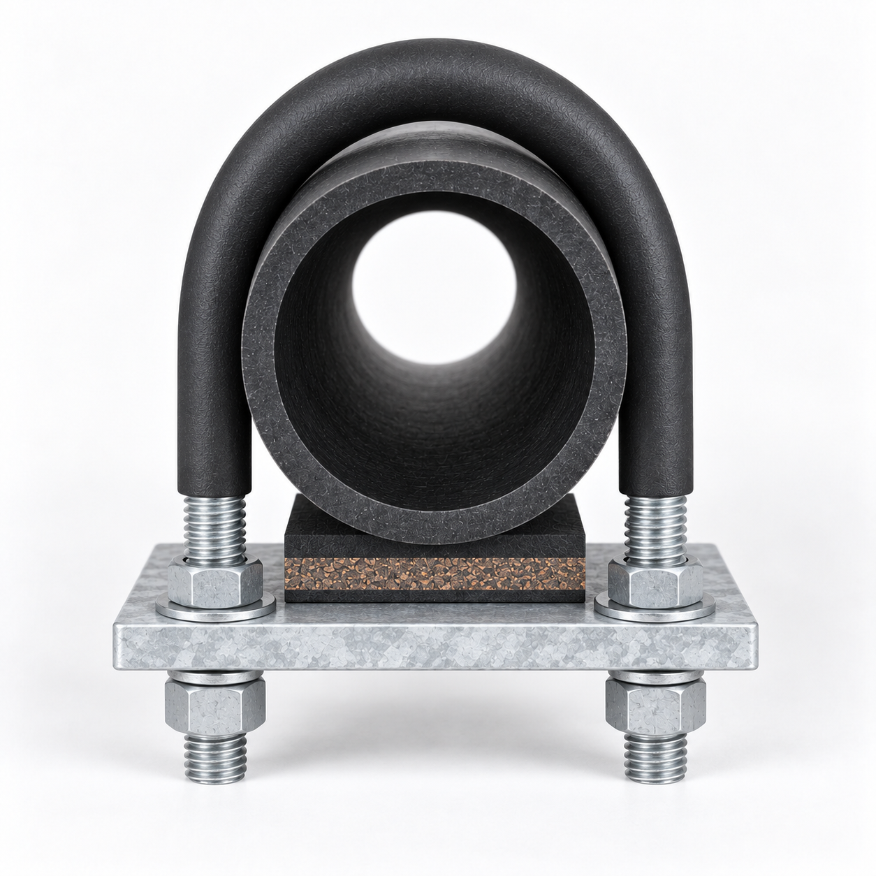
The featured image is a generated representative of an insulated HDPE pipe U-bolt assembly. It illustrates a black HDPE pipe sample, sleeved round U-bolt, broad metal plate, composite bearing pad, washers, and four nuts. It does not prove a material grade, exact dimensions, pad formulation, coating specification, load capacity, temperature limit, standard compliance, test result, certification, or previous project supply.
Request a Drawing-Based Quotation
Send YOUNGLEE the actual pipe outside diameter and dimensional standard, DR or SDR, service temperature, filled weight, support spacing, required grip or guide behavior, calculated loads and movement, U-bolt geometry, support-plate detail, isolation materials, metal grade, finish, hardware, quantity, inspection plan, and approved drawing. YOUNGLEE will review custom dimensions, materials, coatings, insulation, threads, and production requirements before quotation. Final suitability and system performance remain subject to project engineering approval.
Reference Design Checks for Above-Ground HDPE
| Design question | Why it affects the clamp | Required project input |
|---|---|---|
| What load reaches each support? | Pipe weight, fluid weight, fittings, valves, insulation, and dynamic effects influence bearing and hardware reactions | Operating, empty, test, occasional, and installation load cases |
| What is the support spacing? | Span affects bending stress and sag; spacing cannot be selected from clamp diameter alone | Pipe OD and ID, DR or SDR, material, service temperature, pressure condition, fluid density, and deflection criterion |
| Can the pipe move axially? | HDPE has a higher thermal expansion response than rigid metal piping; an unintended grip can change the system load path | Temperature range, calculated travel, guide direction, friction basis, anchor locations, and available clearance |
| How broad is the bearing surface? | A broader, smooth contact can reduce point loading and surface damage | Required wrap angle, contact length, plate radius, pad system, and allowable local deformation |
| Are chemicals, UV, or hydrocarbons present? | Exposure can affect the HDPE, elastomer, adhesive, coating, and pad over time | Fluid and external environment, concentration, temperature, exposure duration, UV condition, and compatibility approval |
| What happens at fittings and rigid transitions? | Heavy or rigid components may need separate support so their reactions are not imposed on a flexible span | Fitting weights, transition details, nearby support locations, and piping stress review |
Customization Note: The checks above are a quotation and design-review checklist, not calculated capacities. Support spacing, contact area, loads, movements, and allowable pipe deformation are project-specific and must be established by the responsible engineer and pipe manufacturer data.
As a general industry reference, PPI’s above-ground PE guidance states that supports acting as cradles rather than clamps should be smooth, should support at least 120 degrees of the pipe, and should have a contact length of roughly one-half to one pipe diameter. That guidance is useful when designing the lower bearing interface, but it must not be copied automatically onto every U-bolt assembly. A narrow hold-down plate, a broad cradle, and a fixed restraint have different load paths and require different calculations.
Materials, Isolation, and Corrosion Protection
Carbon-steel U-bolts offer a practical custom-manufacturing basis and may be zinc plated, hot-dip galvanized, or supplied with a project coating. Stainless steel can be considered for corrosive environments, but grade selection, galling control, nut compatibility, and isolation from adjacent metals still require review. Coating choice must account for thread fit, installation damage, field repair, contact with elastomers, and exposure at cut or formed surfaces.
Neoprene is one possible contact insulation, not a universal answer. Buyers should specify the required compound or performance basis, including hardness, thickness, compression behavior, temperature range, chemical resistance, weathering, fire requirements, and documentation. Cork-neoprene or another composite may be used below the pipe to distribute contact, but its long-term compression and environment must match the project. Do not infer these properties from color.
For metal-pipe arrangements and broader sleeve choices, see YOUNGLEE’s insulated U-bolt overview. Where a machined isolation support bar is the specified load-bearing component, compare the separate phenolic laminate support-bar U-bolt assembly. A rigid stanchion carrying a formed metal saddle follows a different load path, described on the pipe saddle support with U-bolt page.
Manufacturing and Inspection Points
YOUNGLEE can manufacture the bent rod, threads, plate, pad interfaces, nuts, and washers to an approved drawing. The manufacturing route should control rod or bar identity, forming dimensions, bend condition, thread form, straight-leg parallelism, coating allowance, plate-hole alignment, rounded contact edges, and assembly fit. Isolation components should be identified separately from the metal grade and coating.
Inspection may include material certificates when ordered, dimensional reports, thread gauging, coating records, visual examination, pad material certificates, sample assembly, and packaging controls. Any load test, salt-spray exposure, low-temperature qualification, chemical-resistance test, fire test, or certification must be specified before quotation. It is not included or claimed merely because a material or coating name appears in the description.
Installation Considerations
- Confirm that the support plate is aligned and that no burr, weld spatter, sharp edge, or trapped debris contacts the pipe.
- Install the specified pad and sleeve without folds, gaps at the contact area, or damage. The sleeve should meet the start of each threaded section without covering the threads.
- Use the approved washer and nut sequence. Do not tighten by habit when the drawing controls clearance or installed dimension.
- Check that a guide can move in the intended direction and that stops, adjacent supports, or structure do not block the calculated travel.
- Recheck pipe shape, pad position, nut locking, thread projection, and coating condition after assembly and during the project’s specified inspection interval.